
Temperature sensor and heating system using same

A temperature sensor and positive temperature coefficient technology, applied in the field of heating systems, can solve the problems of difficult to maintain PTC characteristics for a long time, easy degradation of PTC devices, etc., and achieve the effect of excellent durability and reduced installability

Inactive Publication Date: 2007-02-07
ジェイビーエイチ
View PDF0 Cites 4 Cited by
  • Summary
  • Abstract
  • Description
  • Claims
  • Application Information

AI Technical Summary

Problems solved by technology

However, it has a disadvantage that the PTC device is easily degraded since a strong heating current is repeatedly applied to the PTC device, which makes it difficult to maintain the PTC characteristics for a long time

Method used


Image

  • Temperature sensor and heating system using same
  • Temperature sensor and heating system using same
  • Temperature sensor and heating system using same

Examples


Embodiment Construction

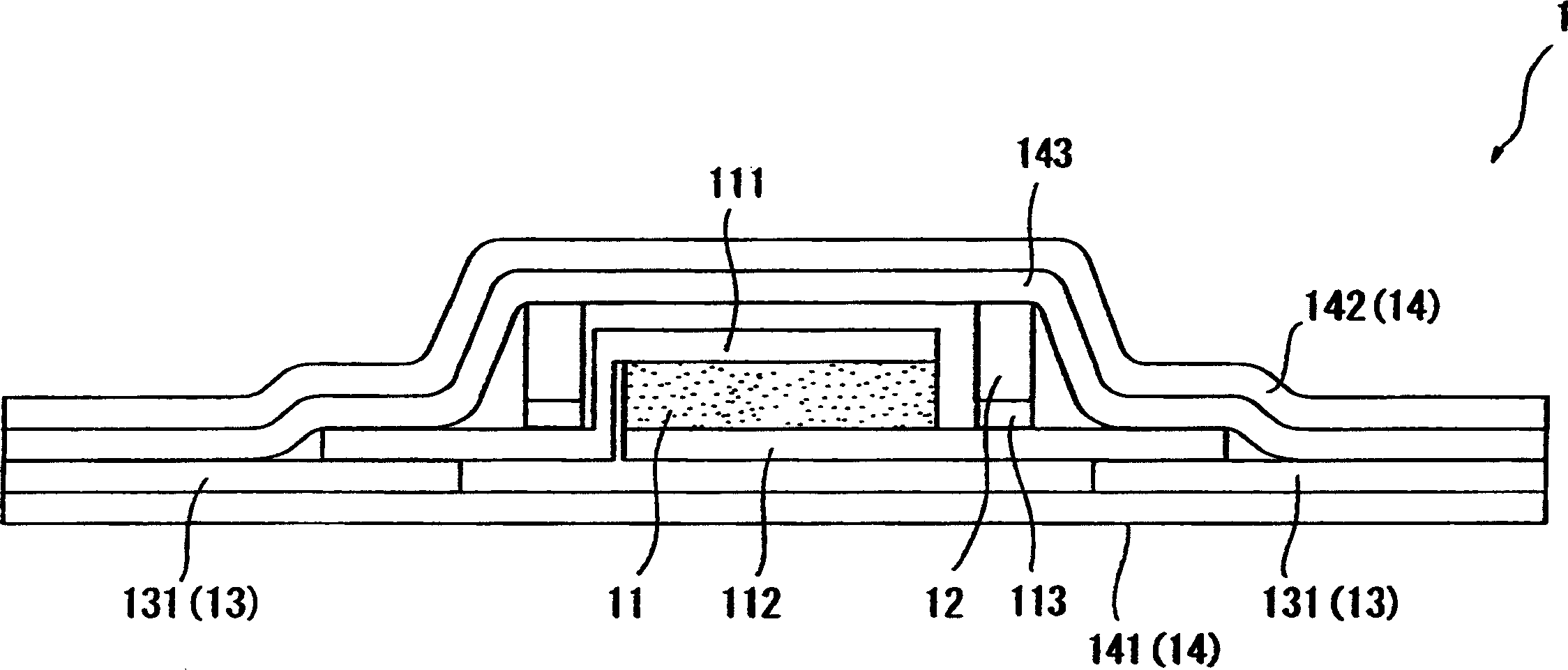
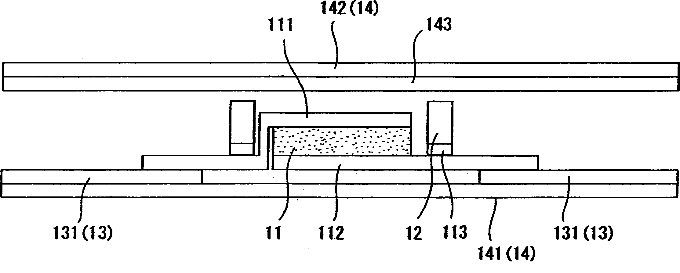
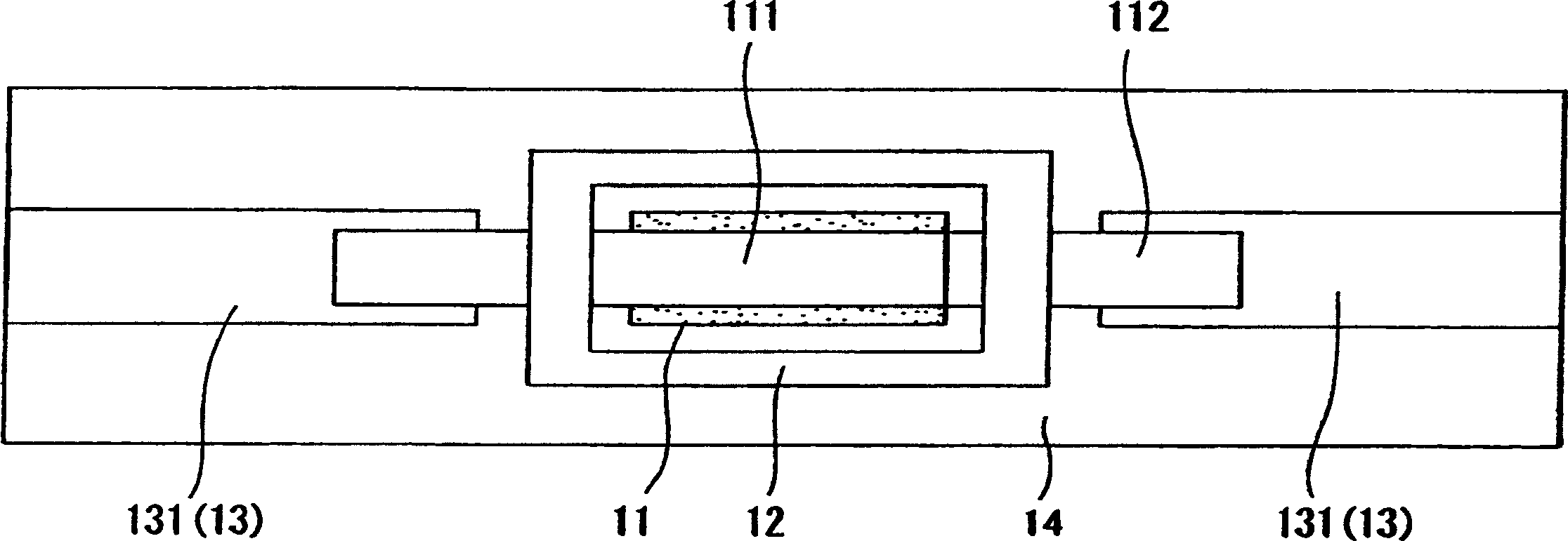
[0022] Embodiments of the present invention will now be described by referring to the accompanying drawings. Figure 1 to Figure 3 A temperature sensor according to a first embodiment of the present invention is described. exist figure 1 Among them, the temperature sensor 1 has a plurality of temperature detection chips 11, a pressure-resistant element 12 for protecting the temperature detection chips 11, a temperature detection signal cable 13 for connecting these temperature detection chips 11 in series, and a temperature sensor unit 16 for controlling the temperature sensor 1 (see attached Figure 4 ).

[0023] Such as figure 2 with image 3 As shown in , each temperature detection chip 11 is made of a device with PTC (positive temperature coefficient) characteristics (abbreviated as PTC device), and is shaped into a rectangle or a circle, and the upper surface and the lower surface of the chip are attached with lead terminals 111, 112. The upper lead terminal 111 is ...


PUM


Abstract

A temperature sensor of a simple construction using PTC devices which efficiently detects a temperature in a wide area of a planar heater is realized. The temperature sensor has excellent durability, manufacturability and installability and can be manufactured at reduced cost. For this purpose, the temperature sensor comprises a plurality of temperature detection chips formed flat, each using a PTC device, enclosed by a pressure resisting member, and connected in series by a temperature detection signal cable. The temperature sensor is further laminated between layers of an insulating film and, as a whole, formed like a ribbon.

Description

technical field [0001] The present invention relates to a temperature sensor for detecting temperature changes in a flat heater for floor heating and various other heating, and to a heating system using the temperature sensor. Background technique [0002] Various planar heaters are known for use in electric floor heating systems. A conventional example has rope heaters arranged in a zigzag on a plane of a predetermined size (for example, Patent Document 1). Another conventional example has a heating material mainly made of carbon printed on a thin layer of an insulating film such as PET (polyethylene terephthalate) in a predetermined width and thickness, at predetermined intervals, and in stripes or tapes. Ethylene glycol formate)) (for example, patent document 2). [0003] Such a floor heating system uses an overheating prevention device or an excessive temperature rise prevention device (for example, Patent Document 1), which uses a bimetal thermostat, a thermal fuse, o...

Claims


Application Information

Patent Timeline
Patent Type & Authority Applications(China)
IPC IPC(8): G01K7/00G01K1/08G01K1/12G01K1/14F24D13/02
CPCG01K1/026F24D13/02G01K7/22Y02B30/00
Inventor 高木量谨中田透杉田茂
Owner ジェイビーエイチ
Learn More