
Rotation detection device

一种旋转检测、旋转角的技术,应用在测量装置、使用电/磁的方法的装置、采用电/磁装置传递传感构件等方向,能够解决装置调整成本上升、多时间、成本上升等问题,达到降低纹波成分的效果

Active Publication Date: 2007-02-07
TOSHIBA ELEVATOR KK
View PDF3 Cites 12 Cited by
  • Summary
  • Abstract
  • Description
  • Claims
  • Application Information

AI Technical Summary

Problems solved by technology

Therefore, there is a problem that the driving device or the control device of the rotary machine becomes complicated, causing a decrease in reliability and an increase in cost.
Among the factors that cause the torque ripple of the motor, in addition to the ripple output by the rotation detection device, there are various factors such as the installation accuracy of the reducer, the operating accuracy of the motor itself, and the high-order harmonics of the magnetic field. The ripple output from the detection device makes it difficult to observe the torque ripple caused by other factors, and it cannot be considered that the function of the sensor as a rotation detection device is fully exerted
[0008] In addition, even in the case of eliminating the ripple component of the rotation detector, it is necessary to adjust the amplitude and phase of the ripple canceling unit in order to eliminate the ripple component well, and the adjustment of the device not only takes a lot of time, but also causes Rise in Adjustment Costs

Method used


Image

  • Rotation detection device
  • Rotation detection device
  • Rotation detection device

Examples


Embodiment Construction

[0104] Hereinafter, embodiments of the present invention will be described in detail with reference to the drawings.

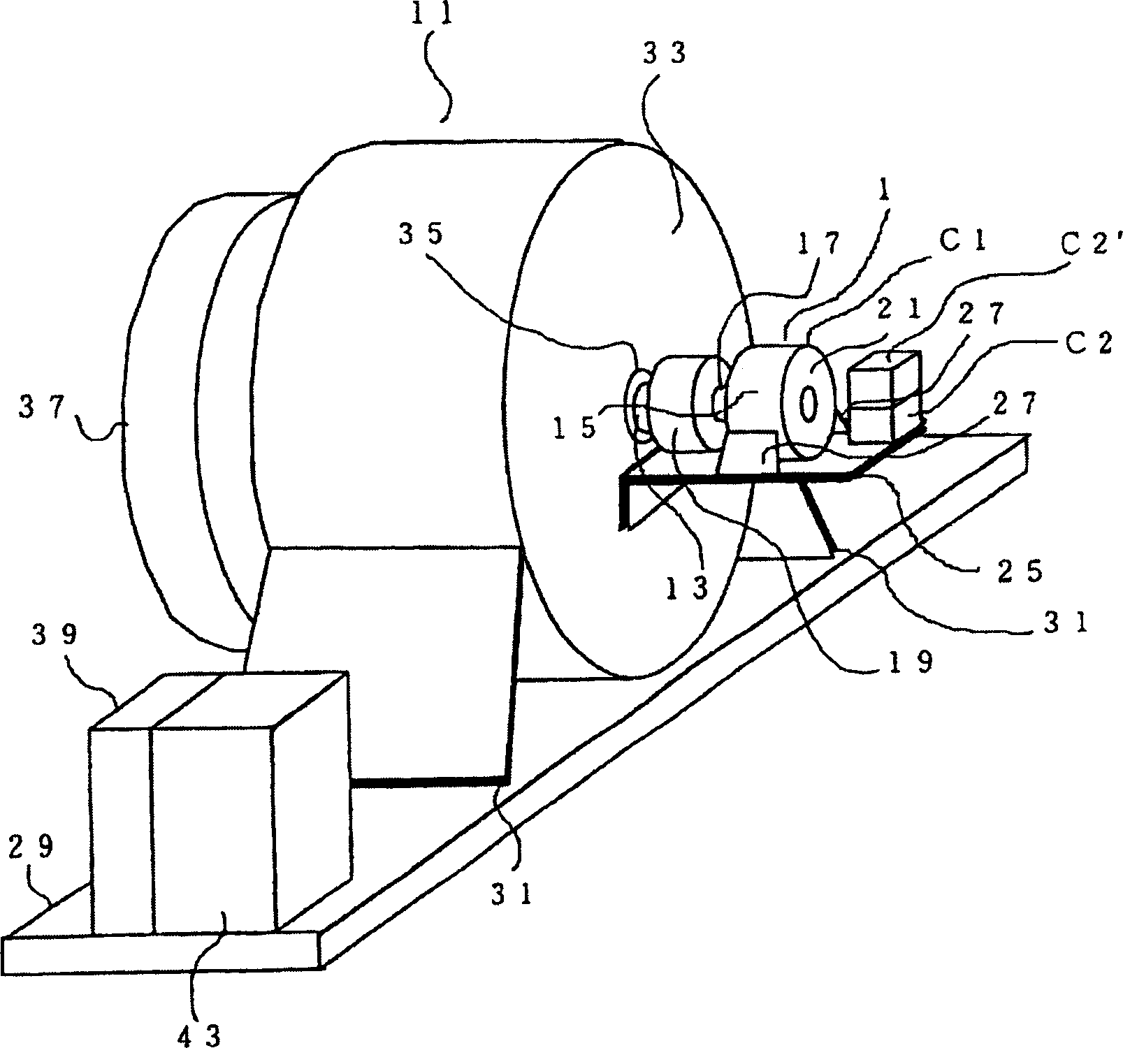
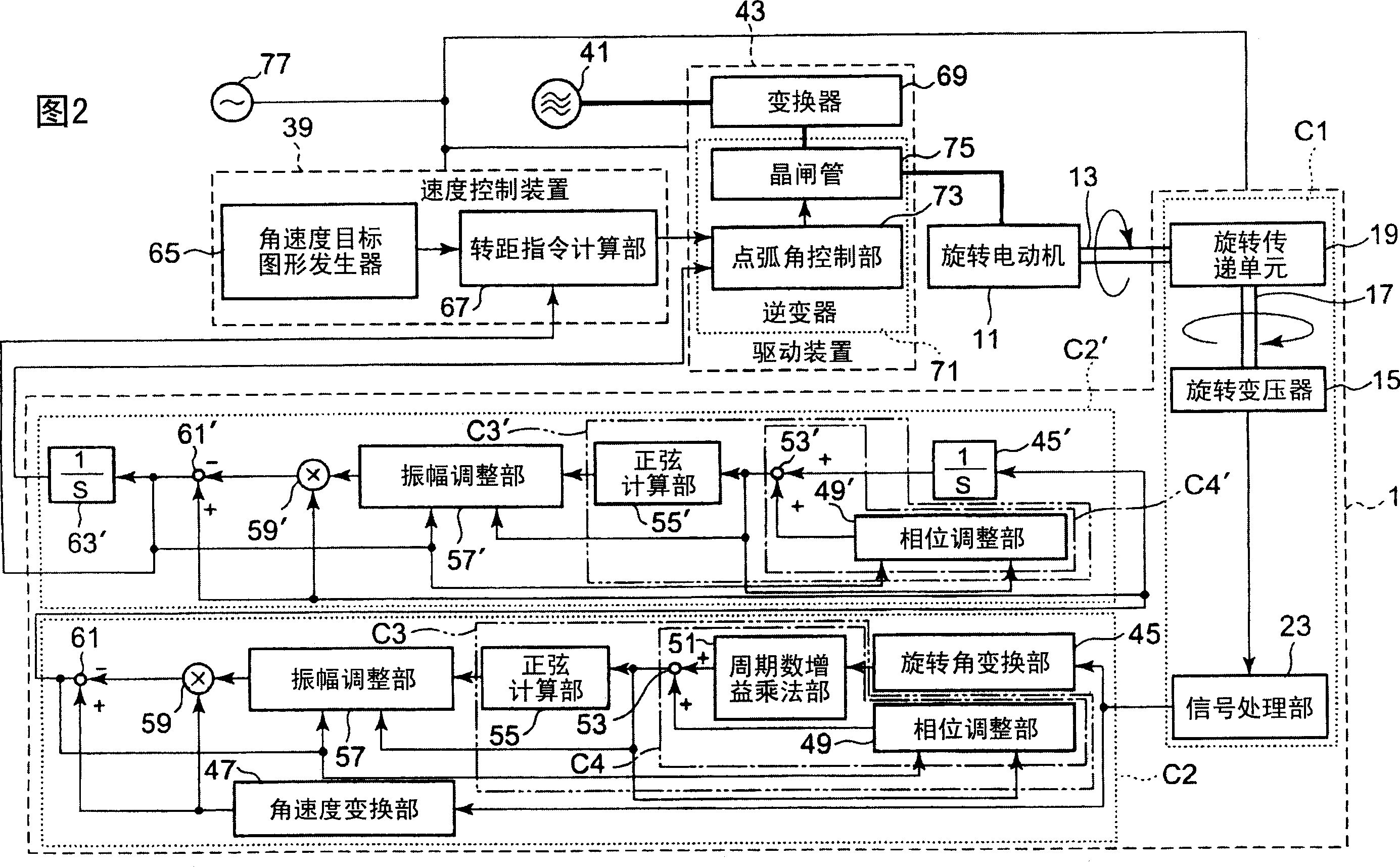
[0105] exist figure 1 In FIG. 4 , the rotation detection device of the first embodiment is indicated by 1 as a whole, and the rotation detection device 1 includes a rotation detection unit C1 and rotation calculation units C2 and C2 ′.

[0106] The rotation detecting unit C1 is composed of a resolver 15 that is mounted on the rotating electric machine 11 as a detection target and outputs a voltage proportional to the rotation angle of the rotor rotating shaft 13 of the rotating electric machine 11, and a rotor (not shown) of the resolver 15 . The directly connected input rotation shaft 17 and the rotation transmission unit 19 that transmits the rotation of the rotor rotation shaft 13 to the input rotation shaft 17 are configured.

[0107] The rotation transmission unit 19 connected with one end of the rotor rotating shaft 13 has, for example, a universal joi...


PUM


Abstract

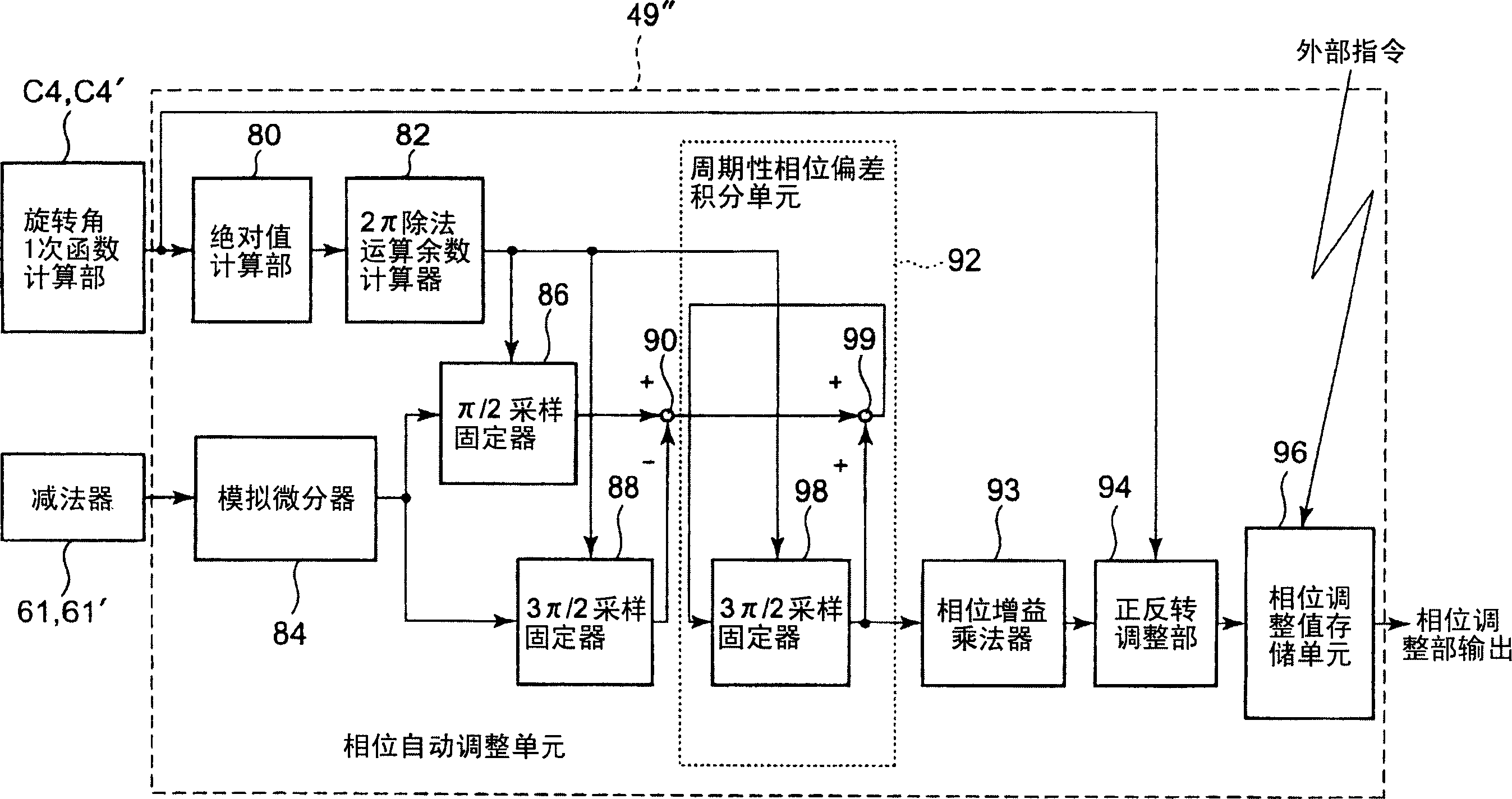
It is possible to reduce torque ripple of a motor attributed to a rotation detection device. A frequency multiplier (51) multiplies a rotation angle theta of a detection object by the ripple frequency m per one rotation of the detection object. An adder (53) adds a phase adjustment value phi from a phase adjustment unit (49) to mtheta. The sin(mtheta + phi) calculated by a sine calculation unit (55) is multiplied by a predetermined gain G by an amplitude adjustment unit (57) and by an angular velocity omega of the detection object by a multiplier (59). A subtractor subtracts an output of the multiplier (59) from the omega and outputs omega(1 - Gsin (mtheta + phi). This output from the subtractor (61) and the output mtheta + phi from the adder (53) are introduced to the phase adjustment unit (49) and the amplitude adjustment unit (57). The phase adjustment unit (49) calculates the phase adjustment value phi according to the accumulated value of the differentiation values outputted from the subtractor (61) sampled for each pi / 2 of output from the adder (53). The amplitude adjustment unit (57) calculates the gain G according to the accumulated value of the difference between the sample value average at 0, pi of the output of the adder (53) and the time integration average value at 0 to pi.

Description

technical field [0001] The present invention relates to a rotation detection device which detects the rotational motion of a rotary machine and which is installed in a control system which controls the operation of the rotary machine based on the detection result of the rotation detection device. More specifically, it relates to a technique for reducing torque ripple of a rotating machine by reducing a ripple component in an output signal of a rotation detection device. Background technique [0002] Typically, there is a torque ripple in the motor. Since torque ripple is the main cause of uneven speed and position error of the servo motor, for example, it becomes the cause of deterioration of machining accuracy in NC equipment, and it becomes the cause of vibration of the car in elevators and damages ride comfort. main reason. Among the torque ripples, there are torque ripples caused by the motor itself including the speed reducer and torque ripples caused by the rotation ...

Claims


Application Information

Patent Timeline
Patent Type & Authority Applications(China)
IPC IPC(8): G01P3/46H02P7/00G01D5/244G01D5/245H02P29/00
CPCG01P3/46
Inventor 森下明平
Owner TOSHIBA ELEVATOR KK
Learn More