Laser beam incident optical device

An optical device, laser technology, applied in the direction of laser, laser welding equipment, laser parts, etc., can solve the problems of increased cost, increased cost, increased number of parts, etc.

An optical device, laser technology, applied in the direction of laser, laser welding equipment, laser parts, etc., can solve the problems of increased cost, increased cost, increased number of parts, etc.

CN1910489AInactive Publication Date: 2007-02-07KK TOSHIBA +1

Image

  • Laser beam incident optical device
  • Laser beam incident optical device
  • Laser beam incident optical device

Examples


Embodiment Construction

[0031] Hereinafter, an embodiment of the present invention will be described with reference to the drawings.

[0032] use Figure 1 to Figure 9 , an embodiment of the laser incident optical device will be described.

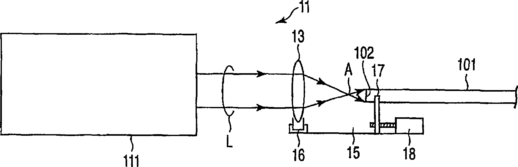
[0033] Such as figure 1 As shown, the laser incident optical device 11 is a pulsed laser light generated by a solid-state laser oscillator (laser device) 111 with a peak power greater than 10 MW without damaging the optical fiber 101, and is injected into the specified laser beam with less loss. The device of the incident end face 102 of the optical fiber 101 with the core diameter and cladding thickness.

[0034] The laser incident optical device 11 has: the condensing lens 13 that condenses the laser light L whose cross-sectional diameter of the beam supplied by the solid-state laser oscillator 111 is a predetermined size; It is an optical fiber position adjustment mechanism 15 at a certain distance.

[0035] The condenser lens 13 is an inexpensive and read...


PUM

PropertyMeasurementUnit
Core diameteraaaaaaaaaa

Abstract

A step-index-type optical fiber (101) made of a material containing quartz, and having a clad thickness 0.035-0.1 times the core diameter and a numerical aperture NA of 0.06-0.22 is used. A laser beam (L) from a giant-pulse-oscillation-system solid laser oscillator (111) having a peak power of over 10 MW is shone divergently to the incident end surface (102) of the optical fiber, whereby enabling a laser beam to be transmitted without damaging the optical fiber.

Description

field of invention [0001] The present invention relates to a laser incident optical device for stably injecting a giant pulse oscillation laser having a peak power of 10 MW or more into an optical fiber. Background technique [0002] Conventionally, in laser ablation processing, laser-induced (Japanese: induced) fluorescence analysis, or laser shock, laser light obtained from a solid-state laser oscillator with a peak power of several MW or higher and a giant pulse (GP) oscillation method has been used. [0003] For lasers with such a large transmission power, for example, a sudden-index optical fiber made of quartz is used. [0004] In the case of continuous oscillation (CW) lasers, optical fibers made of quartz can transmit energy up to several kilowatts. However, in the form of a short-pulse laser with a pulse width of about several nsec, a laser with a pulse energy exceeding tens of mJ has a peak power of several MW or more. [0005] It is known that the pulse energy o...

Claims


Application Information

Patent Timeline
07 Feb 2007
Publication
CN1910489A
IPC
G02B6/42; H01S3/11; B23K26/08
Inventors
石桥诚