Supercharge Your Innovation With Domain-Expert AI Agents!

Scanning probe of atomic force microscope

An atomic force microscope and scanning probe technology, applied in the field of scanning probes, can solve the problems of inconvenient observation and adjustment of laser light spots, and achieve the effect of reducing costs

Inactive Publication Date: 2007-02-14
INST OF ELECTRICAL ENG CHINESE ACAD OF SCI
View PDF0 Cites 9 Cited by
  • Summary
  • Abstract
  • Description
  • Claims
  • Application Information

AI Technical Summary

Problems solved by technology

[0005] The purpose of the present invention is to overcome the defects of the existing atomic force microscope scanning probe which is inconvenient to observe and adjust the laser light spot, and propose an atomic force microscope probe which is more convenient to observe and adjust the laser light spot

Method used


Image

  • Scanning probe of atomic force microscope
  • Scanning probe of atomic force microscope

Examples


Embodiment Construction

[0013] The present invention will be further described below in conjunction with the drawings and specific embodiments.

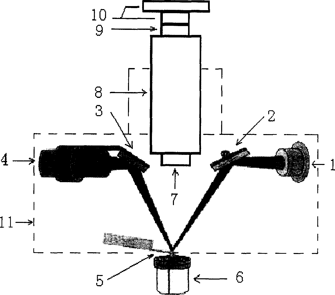
[0014] Such as figure 1 As shown, the scanning probe of the present invention includes a laser 1, a mirror 2, a mirror 3, a four-quadrant photoelectric position detector 4, a micro cantilever 5, an objective lens 7, a focusing lens barrel 8, an eyepiece 9, and a CCD 10. After the laser 1 in the scanning probe emits a laser beam, it will be reflected on the micro cantilever 5 with a needle tip through the mirror 2, and the micro cantilever will reflect the laser light to the four-quadrant photoelectric position detector 4 through the mirror 3.

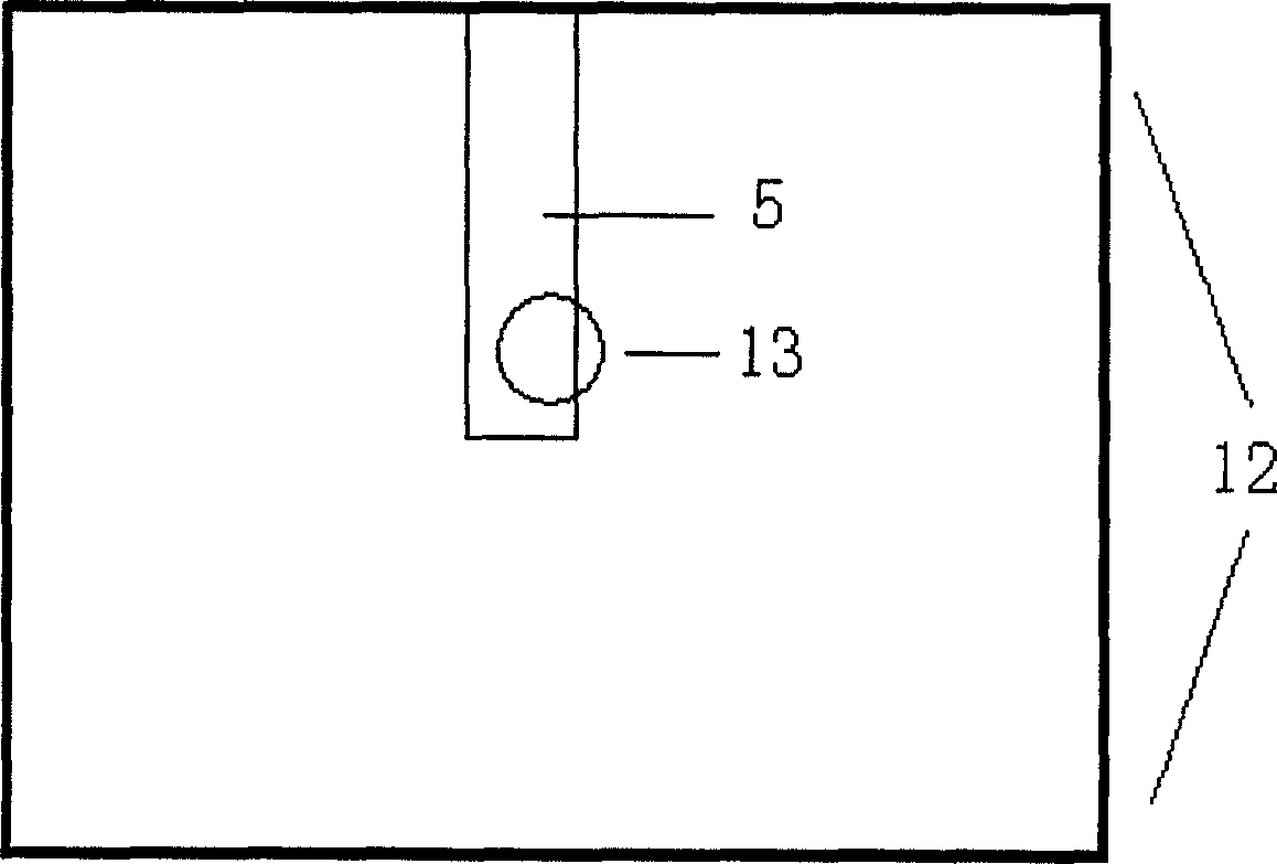
[0015] The focusing lens barrel 8 is an adjustable telescopic lens barrel, which is fixed on the top of the scanning probe housing and is located directly above the micro cantilever 5. The main body of the scanning probe housing 11 is cylindrical, with a diameter of about 100 mm and a height of about 80 mm. The lower pa...


PUM

PropertyMeasurementUnit
diameteraaaaaaaaaa
heightaaaaaaaaaa

Abstract

This invention relates to a scanning probe of an atomic power microscope including a laser, a reflector 2, a reflector 3, a four quadrant photoelectric position detector, a micro-cantilever, a magnifier component and CDD 10, in which, the magnifier component includes magnifier lenses and a focus drawtube, the magnifier lenses include field lens and an ocular, the component is installed just above the micro-cantilever with pinpoints, the focus drawtube is fixed on the top of the scan probe shell to adjust the flex, the upper and lower parts of the drawtube are connected with the field lens and the ocular separately by screw threads, a C-type interface on the ocular is connected with the CCD 10, the output of which is connected to a TV box from outside of the probe then to the computer, amplified micro-cantilever and laser points are displayed by viewing window opened on the computer monitor.

Description

Technical field [0001] The invention relates to a scanning probe of an atomic force microscope. Background technique [0002] The Atomic Force Microscope (AFM) is a professional topography measuring instrument used by humans to conduct scientific research at the nanometer scale. The most basic working principle of the atomic force microscope is: the tip of the force-sensitive flexible cantilever scans the surface of the sample, and the force between the cantilever and the sample surface causes a slight deflection of the cantilever. This deflection is detected and used as a feedback signal. By keeping the force constant, a constant force profile can be obtained. [0003] In order to detect the micro deflection of the cantilever, scientists have developed many different methods, among which the optical lever method is a very simple and effective method. This method has the advantages of stable performance, high accuracy, and linear amplification. The existing AFM scanning probes ar...

Claims


Application Information

Patent Timeline
Patent Type & Authority Applications(China)
IPC IPC(8): G12B21/08G01N13/16G01Q60/24
Inventor 原剑林云生左燕生韩立
Owner INST OF ELECTRICAL ENG CHINESE ACAD OF SCI
Features
  • R&D
  • Intellectual Property
  • Life Sciences
  • Materials
  • Tech Scout
  • Unparalleled Data Quality
  • Higher Quality Content
  • 60% Fewer Hallucinations
Learn More