Power transmission and distribution system of leakage for earth capicitance storage charge and system control method

A technology of capacitance to ground and control method, applied in the direction of protection reacting to fault current, structural association of electrical components, transformer/inductor coil/winding/connection, etc. To achieve the effect of preventing ferromagnetic resonance and delaying the recovery speed

Active Publication Date: 2007-02-14
合肥溢鑫电力科技有限公司
View PDF0 Cites 10 Cited by
  • Summary
  • Abstract
  • Description
  • Claims
  • Application Information

AI Technical Summary

Problems solved by technology

[0005] In the above fault phase arc suppression method, at the moment when the fault phase is grounded in order to judge whether it is an instantaneous fault or to remove the fault, the electric charge will be stored on the capacitance of the system to ground. After the faulty phase, overvoltage occurs during the recovery process of the healthy phase-to-ground voltage, and the power frequency ov

Method used


Image

  • Power transmission and distribution system of leakage for earth capicitance storage charge and system control method
  • Power transmission and distribution system of leakage for earth capicitance storage charge and system control method
  • Power transmission and distribution system of leakage for earth capicitance storage charge and system control method

Examples


Example Embodiment

[0022] Example 1:

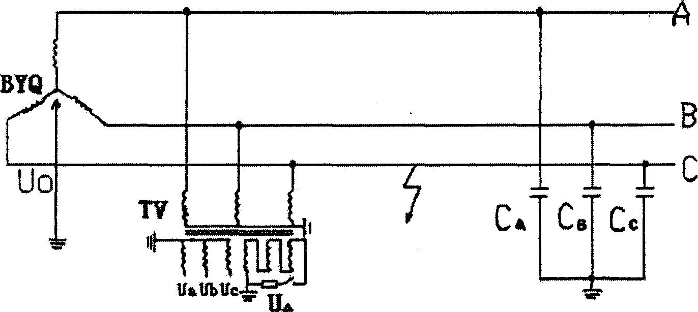
[0023] see figure 1 In this embodiment, a bleeder transformer is set up in the system, specifically a voltage transformer TV with an open triangle is used, and the three-phase windings on the secondary side of the voltage transformer TV are connected end to end and connected in series. The space is set as an opening, and the discharge channel is formed by connecting resistance elements across the two ends of the opening to form a delta connection on the secondary side of the discharge transformer.

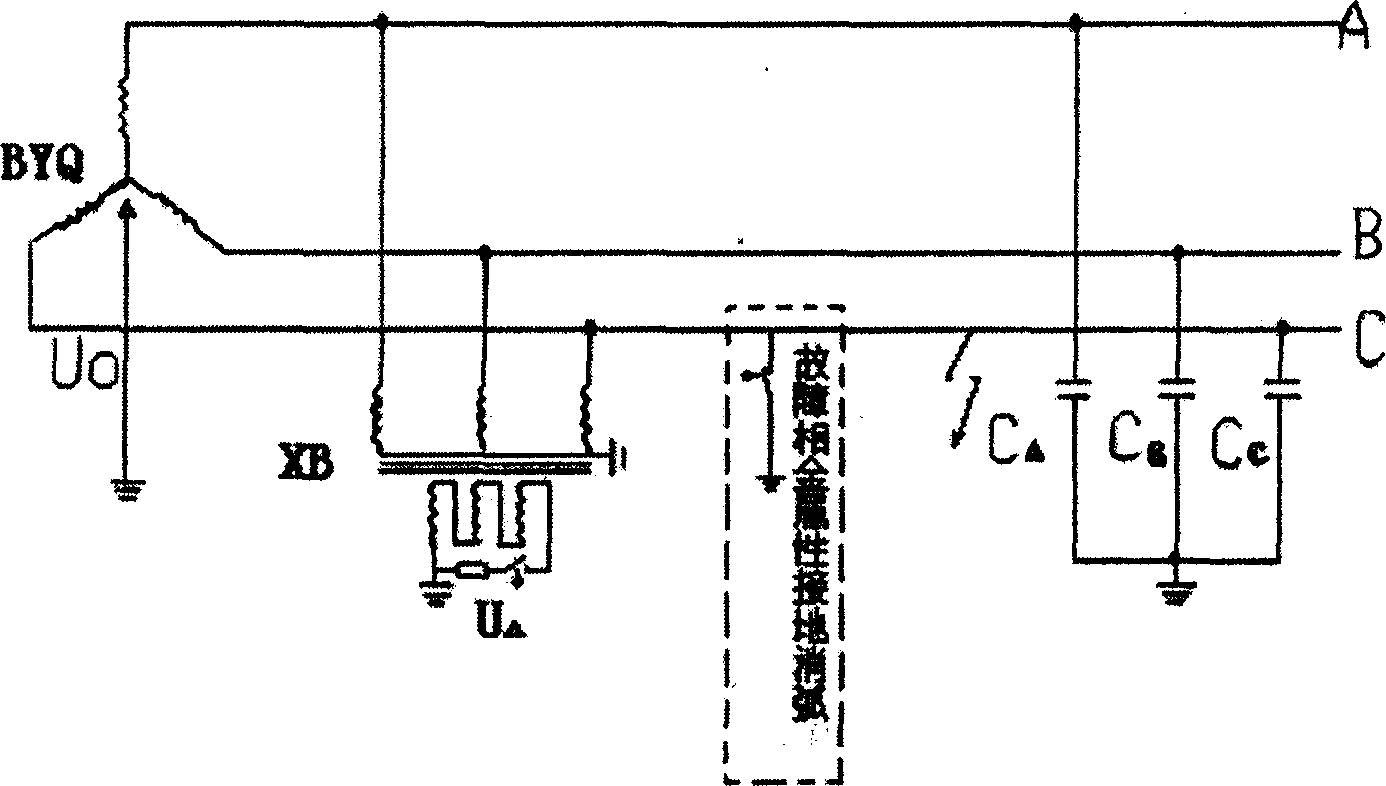
[0024] see image 3 , in the system using the fault phase arc suppression method, including image 3 The system using the fault-phase metallic grounding arc suppression method as shown also includes the system using the fault-phase impedance grounding arc suppression method. For the moment when the arc suppression is released for the purpose of judging the instantaneous fault or eliminating the fault, the system is connected to the ground. Capacitor C A , C ...

Example Embodiment

[0025] Example 2:

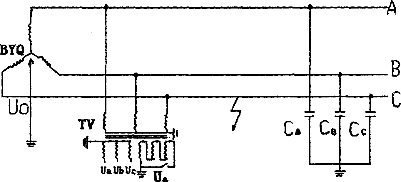
[0026] see figure 2 , and the same as the above-mentioned Embodiment 1, this embodiment is to set a voltage transformer TV with an open triangle as a bleeder transformer in the system, and the three-phase windings of the secondary side of the voltage transformer TV are connected end-to-end and connected in series, wherein An opening is set between any adjacent two-phase windings. The difference from the above-mentioned Embodiment 1 is that the bleeder channel in this embodiment is formed by directly short-circuiting the opening to form a delta connection on the secondary side of the bleeder transformer.

[0027] see Figure 4 , in the system using the fault phase arc suppression method, including Figure 4 The system using the fault-phase metallic grounding arc suppression method as shown also includes the system using the fault-phase impedance grounding arc suppression method. For the moment when the arc suppression is released for the purpose of judgin...


PUM


Abstract

This invention relates to a transmission and distribution system releasing earth capacitor storage charges and a system control method characterizing in setting a releasing transformer in the system, in which, the three phase winding of the secondary side is connected end to end in series, an open-end is set between any adjacent two windings to form a releasing channel by bridging resistor elements at the two ends of the open-end or short-connecting the open-end directly to form a triangle connection of the secondary side, which provides a releasing channel to charges stored to the earth capacitor when the earth system of small current is faulty in earth to prevent from generating over voltage and ferro-resoanace induced in the resuming process of the earth voltage of the faulty phase and sanity phase.

Description

Technical field: [0001] The invention relates to a protection system and a protection method for a small current grounding system. Background technique: [0002] There are two types of arc suppression methods for small current grounding systems, or neutral point ungrounded systems, one is neutral point arc suppression, such as the arc suppression method in which the neutral point is grounded through an arc suppression coil; the other type is the neutral point arc suppression method. It is fault phase arc suppression. The fault phase arc suppression method means that when a single-phase grounding occurs in a small current grounding system, the fault phase is directly grounded through switching elements such as contactors and thyristors, or the impedance is put in between the fault phase and the ground. between, implement arc suppression. [0003] There are two types of single-phase grounding for small current grounding systems, permanent grounding and non-permanent grounding...

Claims


Application Information

Patent Timeline
IPC IPC(8): H02H3/16H01F27/28H01F27/40
Inventor 张云一
Owner 合肥溢鑫电力科技有限公司
Why Eureka
Try Eureka