Anti-resonance voltage transformer and manufacturing method thereof
A resonant voltage, transformer technology, applied in the transformer field, can solve problems such as transformer damage, achieve the effect of simple and easy size, and avoid ferromagnetic resonance
- Summary
- Abstract
- Description
- Claims
- Application Information
AI Technical Summary
Problems solved by technology
Method used
Image
Examples
Embodiment 1
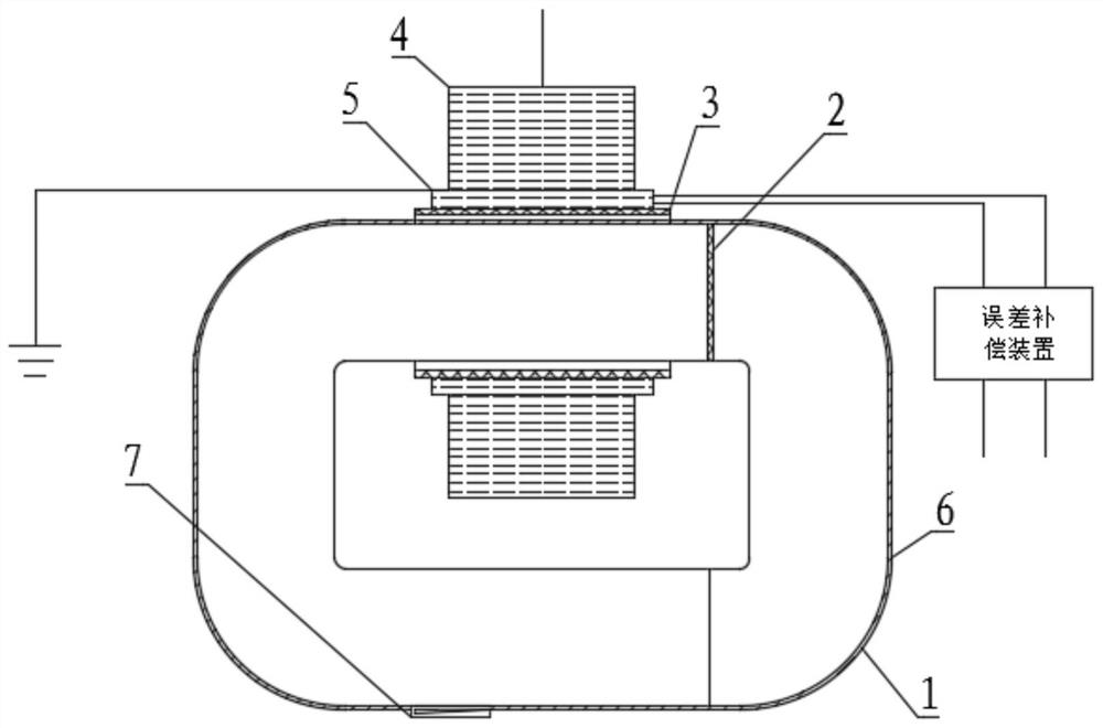
[0039] Please refer to figure 1 , an anti-resonance voltage transformer in this embodiment includes an iron core 1 and a round-shaped insulating frame 3. Specifically, the iron core 1 is a square-shaped iron core 1, and the iron core 1 is cut from a position 30 mm away from one side of the iron core 1. It is divided into two halves, A and B, so that the core 1 can pass through the center of the insulating frame 3 so that the insulating frame 3 can be set on one side of the core 1, wherein the inner diameter of the insulating frame 3 is 1 to 5 mm larger than the outer diameter of the iron core 1, ensuring The iron core 1 fits smoothly and the gap between the iron core 1 and the skeleton is small, and the overall volume of the product is small.
[0040] A secondary winding 5 is wound on the insulating frame 3, and the secondary winding 5 is formed by winding enamelled copper flat wire directly on the insulating frame 3, and three layers of insulating paper are wrapped on the sec...
Embodiment 2
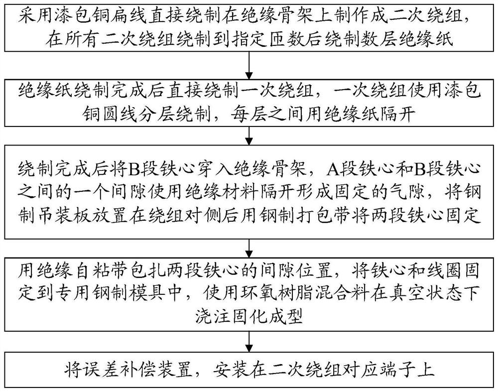
[0046] Please refer to figure 2 , a method of manufacturing an anti-resonance voltage transformer in this embodiment, using enamelled copper flat wire to be directly wound on the insulating frame 3 to form a secondary winding 5, after all the secondary windings 5 are wound to a specified number of turns Wind several layers of insulating paper, preferably 0.07 thick capacitor composite paper wound three layers.
[0047] After the insulating paper is wound, the primary winding 4 is directly wound. The primary winding 4 is wound in layers using enamelled copper round wires, and each layer is separated by insulating paper.
[0048] After the winding is completed, the B-section iron core 1 is penetrated into the insulating skeleton 3. A gap between the A-section iron core 1 and the B-section iron core 1 is separated by an insulating material 2 to form a fixed air gap. The air gap is preferably 1mm. After the hoisting plate 7 is placed on the opposite side of the winding, the tw...
PUM
 Abstract
Description
Claims
Application Information
 - R&D
- Intellectual Property
- Life Sciences
- Materials
- Tech Scout
- Unparalleled Data Quality
- Higher Quality Content
- 60% Fewer Hallucinations
Browse by: Latest US Patents, China's latest patents, Technical Efficacy Thesaurus, Application Domain, Technology Topic, Popular Technical Reports.
© 2025 PatSnap. All rights reserved.Legal|Privacy policy|Modern Slavery Act Transparency Statement|Sitemap|About US| Contact US: help@patsnap.com


