Control circuit of construction machine

A control circuit and construction machinery technology, applied in mechanical equipment, construction, servo meter circuits, etc., can solve problems such as bad user claims, inefficiency, and deterioration of operability, so as to improve level leveling workability, suppress labor and costs, The effect of improving reliability

Inactive Publication Date: 2007-02-14
SHIN CATERPILLAR MITSUBISHI LTD CORP
View PDF1 Cites 20 Cited by
  • Summary
  • Abstract
  • Description
  • Claims
  • Application Information

AI Technical Summary

Problems solved by technology

[0022] Even when adjusting with a standard bucket, depending on the weight and type of the bucket attachment, the timing and speed of the boom cylinder and the arm cylinder are different for the same movement command, and the operability deteriorates.
[0023] In addition, it is inefficient to carry out the adjustment design, production and evaluation test of the spool notch of the individual countermeasure type every time for user complaints such as poor soil preparation.
[0024] And, all the while, the inherent characteristics of the open center have been abandoned, and the potential disadvantages contrary to the advantages of the open center circuit, such as gyrodynamic force modulation, etc., have not been eliminated until now
[0025] Moreover, it also has the disadvantage that it cannot eliminate the operational load influence in the material lifting operation, and it tends to rely on the operator's proficiency, which is prone to failures caused by human errors.

Method used


Image

  • Control circuit of construction machine
  • Control circuit of construction machine
  • Control circuit of construction machine

Examples


Embodiment Construction

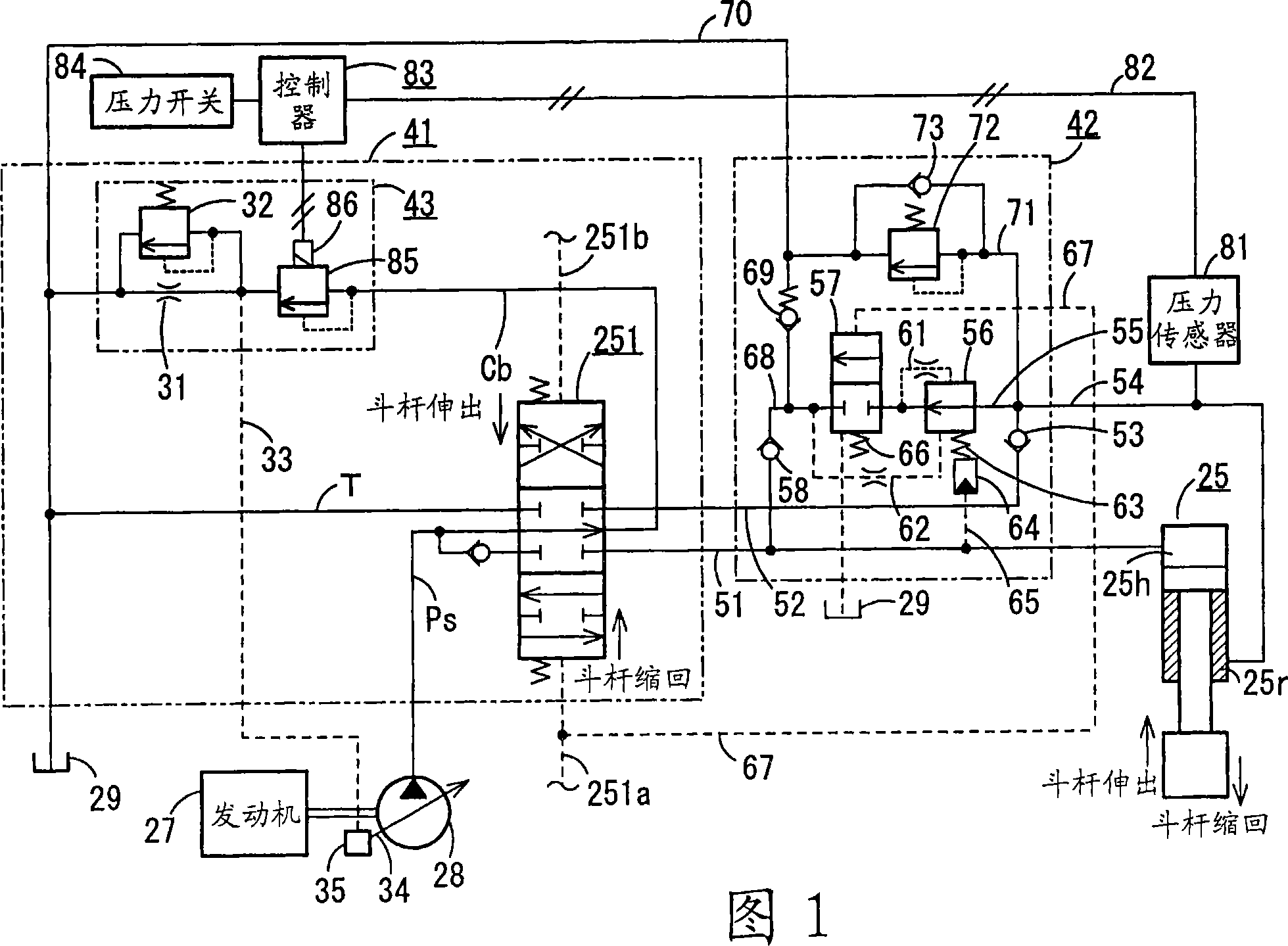
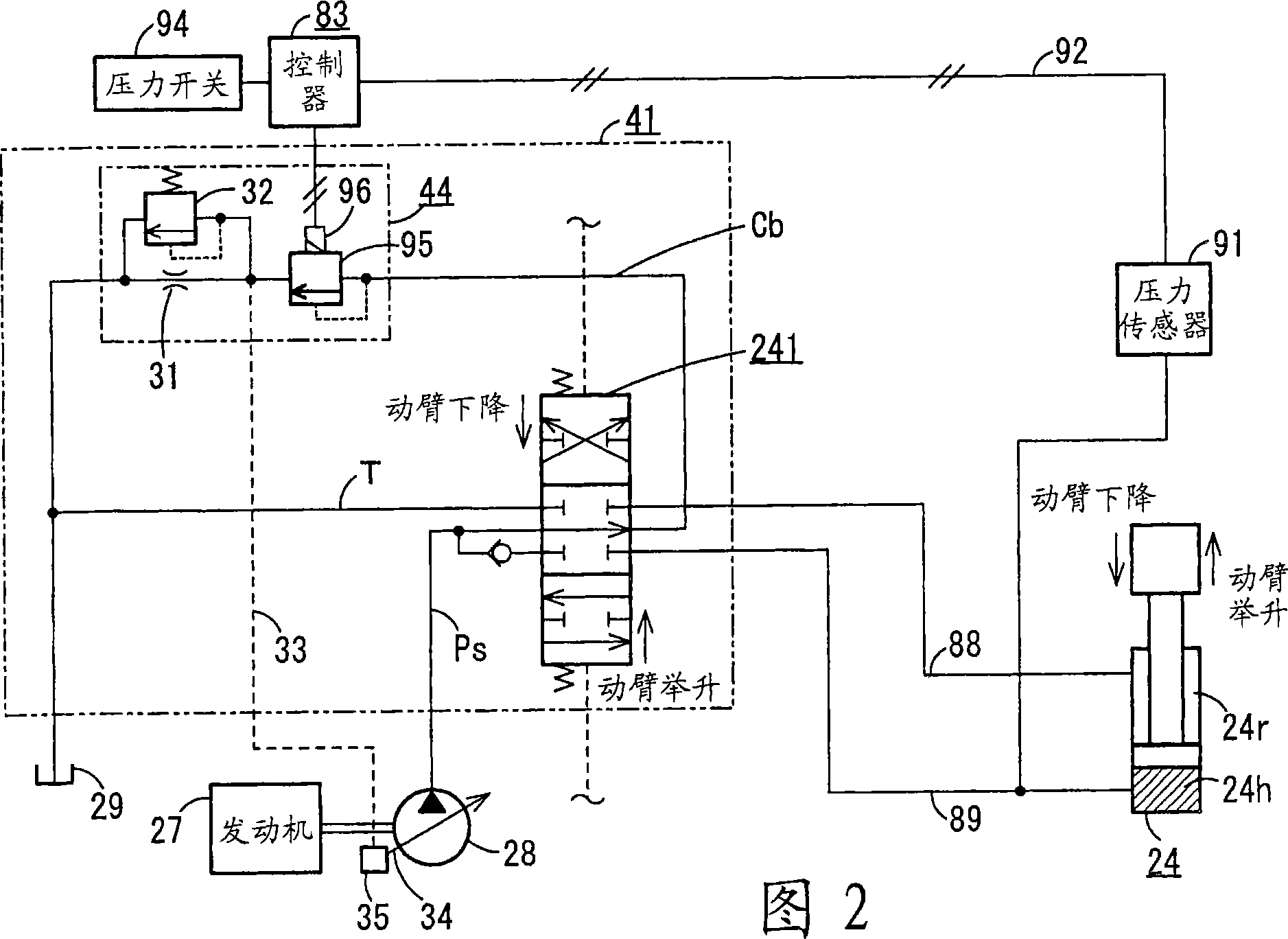
[0046] Hereinafter, the present invention will be described with reference to one embodiment shown in FIGS. 1 to 4 . in addition, Figure 5 The illustrated circuits are basic circuits that serve as the premise of the present invention, and descriptions thereof may be omitted by attaching the same symbols to the same parts, and the circuits of the traveling system, swing system, and bucket system are omitted because they are the same.

[0047] Figures 1 and 2 show the Figure 5 The load pressure compensation system in the middle opening system of the two pumps shown here, while taking advantage of the characteristics of the current middle opening system, partially performs load pressure compensation to improve the leveling performance and production in the use of large and heavy buckets performance, and the lifting operability when lifting materials.

[0048] In Fig. 1 and Fig. 2, 41 is a control valve, which is equipped with Figure 5 Spools of various operating valves 111 , 1...


PUM


Abstract

A control circuit of a construction machine capable of securing a same operability as in a case where a hydraulic shovel having an open center circuit is tuned by using a standard bucket even when the bucket weight of the hydraulic shovel is changed. Center bypass lines (Cb) are installed for a boom operation valve and a stick operation valve (251) controlling an oil supplied from a hydraulic pump (28) to a boom cylinder and a stick cylinder (25). A stick-in meter-out load pressure compensating valve (42) is installed in a rod side return line (55) from the rod side (25r) of the stick cylinder (25) to a tank (29). A pressure sensor (81) detecting the pressure of the hydraulic oil supplied to the rod side (25r) is installed on the rod side (25r) of the stick cylinder (25). An electromagnetic proportional relief valve (85) controlling a center bypass line pressure on the downstream side of the stick operation valve (251) in an increasing direction according to the rise of the pressure detected by the pressure sensor (81) is installed in the center bypass line (Cb).

Description

technical field [0001] The invention relates to a control circuit of a construction machine having an open center circuit provided with center bypass lines. Background technique [0002] Figure 5 A conventional hydraulic circuit used in a hydraulic excavator (swing type) is shown, and the following parts are taken as control objects, that is, two traveling motors 11 with brakes on the left and right for driving the lower traveling body (crawler belt), 12. The revolving motor 13 used to make the upper revolving body revolving relative to the lower traveling body, and the front working device 14 ( Figure 6 ) operation of the following various hydraulic cylinders. [0003] Such as Figure 6 As shown, the front working device 14 connects the boom 15, the arm 16 and the bucket 17 through pins 21, 22, and 23 in sequence, and then the boom 15 is rotated by the boom cylinder 24, and the arm 16 is rotated by the arm cylinder 25. , Bucket 17 is rotated by bucket oil cylinder 26. ...

Claims


Application Information

Patent Timeline
Patent Type & Authority Applications(China)
IPC IPC(8): E02F9/22F15B11/00F15B11/028
CPCE02F9/2235F15B11/16F15B2211/7053E02F9/2282E02F9/2292F15B2211/20523F15B2211/633F15B2211/6313F15B2211/50518F15B2211/526E02F9/2296F15B2211/6653F15B2211/50545F15B2211/513E02F9/2203F15B2211/3116F15B2211/20546E02F9/2228F15B2211/6656F15B2211/555E02F9/22F15B11/028F15B11/00
Inventor 吉野和宪
Owner SHIN CATERPILLAR MITSUBISHI LTD CORP
Why Eureka
Try Eureka