High frequency coupler, high frequency tansmitter and antenna

A high-frequency coupler and high-frequency transmission technology, which is applied in the field of high-frequency couplers, can solve the problems of insufficient electrical coupling, etc., and achieve the effect of improving the magnetic induction coupling state and excellent transmission characteristics

Inactive Publication Date: 2007-02-14
樋口 俊昭 +2
View PDF0 Cites 14 Cited by
  • Summary
  • Abstract
  • Description
  • Claims
  • Application Information

AI Technical Summary

Problems solved by technology

[0007] However, in a planar configuration in which the antenna and the balun circuit are formed on the same plane, sufficient electrical coupling cannot be obtained at the coupling portion between the balanced line and the unbalanced line.

Method used


Image

  • High frequency coupler, high frequency tansmitter and antenna
  • High frequency coupler, high frequency tansmitter and antenna
  • High frequency coupler, high frequency tansmitter and antenna

Examples


Embodiment Construction

[0043] Hereinafter, the present invention will be described in detail with reference to the drawings.

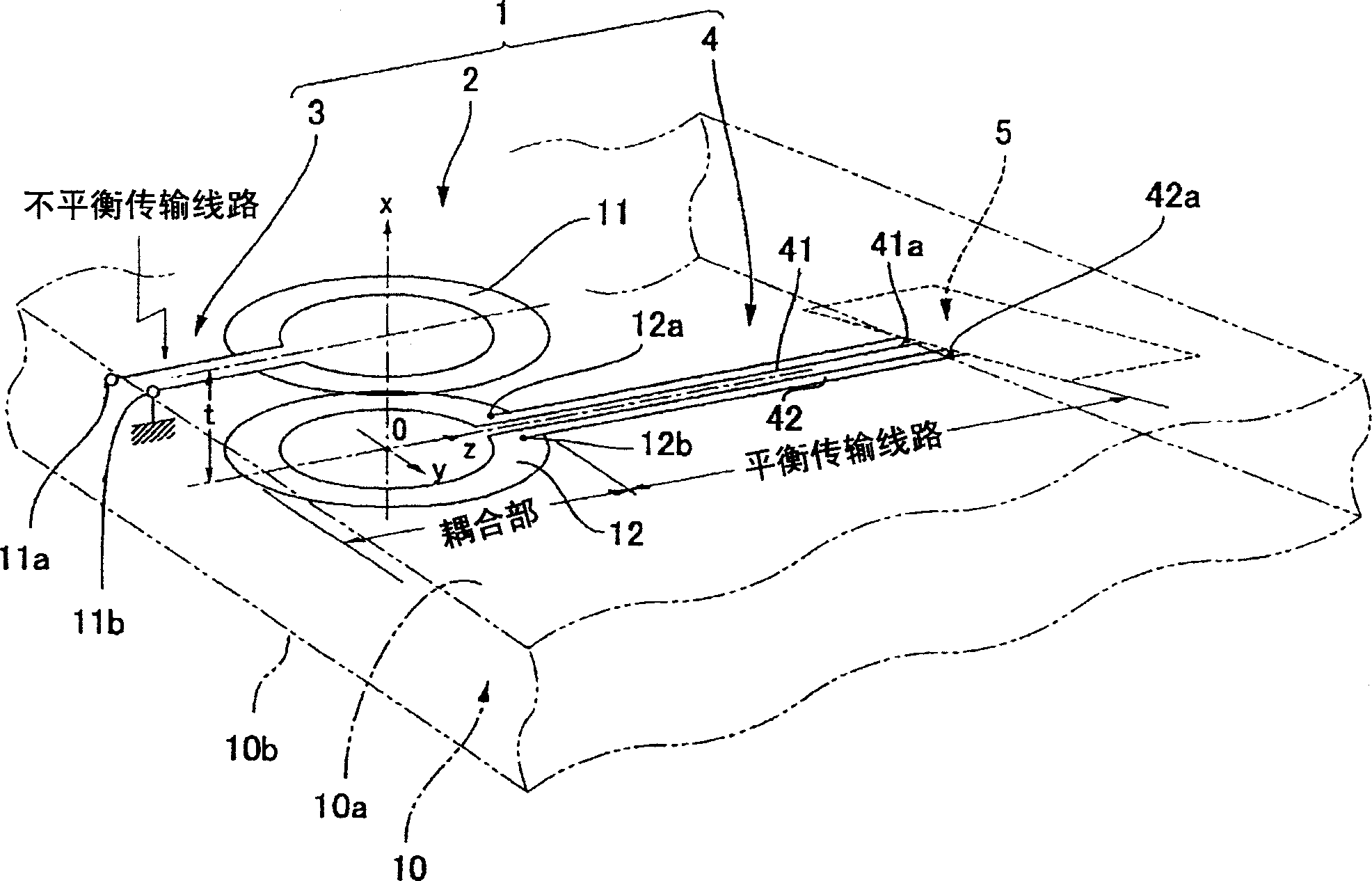
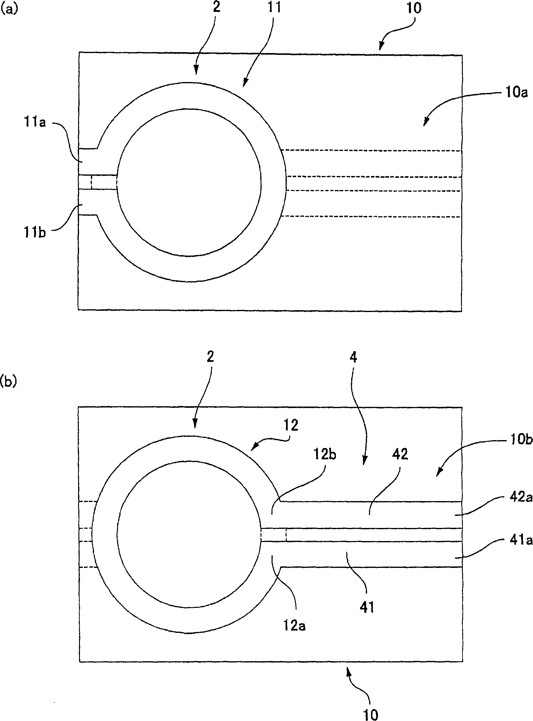
[0044] figure 1 An explanatory diagram showing a high-frequency transmitter to which the present invention is applied. figure 2 (a) and (b) are its back view and plan view. The high-frequency transmitter 1 of the present embodiment has a high-frequency coupler 2 through which an unbalanced transmission line 3 and a balanced transmission line 4 are coupled to each other.

[0045] The high-frequency coupler 2 has a circuit board 10 formed of a dielectric. On the back surface (first substrate surface) 10a of the circuit board 10, a ring-shaped first coupling portion pattern 11 is formed by copper foil or the like. Also on the surface (second substrate surface) 10b, an annular second coupling portion pattern 12 with one disconnection is formed from the same copper foil. The first and second coupling portion patterns 11 and 12 are, for example, the same ring shape.

[0046...


PUM


Abstract

The present invention provides a high frequency coupler(2) comprising first and second coupler patterns(11, 12) each having an annular shape broken at one location and formed, facing each other, on the front and rear surfaces of a circuit board(10) consisting of a dielectric and being t thick. The terminals(11a, 11b) of the first coupler pattern(11) serve as unbalanced terminals, and the terminals(12a, 12b) of the second coupler pattern(12) serve as unbalanced terminals from which coplanar lines(41, 42) are led out along the rear surface and connected with a balanced antenna(5). Since the first and second coupler patterns(11, 12) are kept in an electrostatic capacity coupling state as well as in a magnetic induction coupling state, the coupler high in transmission efficiency in a broad band can be realized.

Description

technical field [0001] The present invention relates to a high-frequency coupler for two or more high-frequency transmission lines with different coupling properties, a high-frequency transmitter including the high-frequency coupler, and an antenna including the high-frequency coupler. Background technique [0002] Since the input and output parts of electronic circuits that process high-frequency signals (RF) are often unbalanced transmission lines that are grounded on one side, unbalanced coaxial lines or microstrip lines are used for transmission cables directly connected to their terminals. . On the other hand, since antennas such as dipole antennas and loop antennas are balanced antennas, a balun circuit for impedance conversion is required between the antenna and the transmission cable. [0003] In the past, in the reception of TV broadcasting, etc., copper wires were used to wind Figure 6 (a) Transformer on a glasses-shaped ferrite core shown. On the other hand, in...

Claims


Application Information

Patent Timeline
Patent Type & Authority Applications(China)
IPC IPC(8): H01P5/10H01P5/18
CPCH01P5/10H01P5/18
Inventor 畑宏唐鎌隆久
Owner 樋口 俊昭
Why Eureka
Try Eureka