
Air conditioner device

An air-conditioning, outdoor-side technology, used in compressors with reversible cycles, compressors, damage protection, etc., can solve problems such as refrigerant noise, increased pressure loss, and increased piping diameter, achieving high reliability, oil Small fluctuation and small pressure fluctuation effect

Inactive Publication Date: 2007-02-21
PANASONIC CORP
View PDF1 Cites 26 Cited by
  • Summary
  • Abstract
  • Description
  • Claims
  • Application Information

AI Technical Summary

Problems solved by technology

[0004] In this defrosting method, there is the following basic problem: Since the heat exchanger on the inside of the room becomes an evaporator during defrosting, the temperature of the room in the room drops and a feeling of cool air is felt.
[0014] Therefore, this refrigeration cycle requires four two-way valves, which is a complicated and expensive method
[0015] In addition, since the refrigerant used for defrosting and the refrigerant dissipated in the indoor heat exchanger 110 merge, if the pressure of the refrigerant at the junction is higher than the pressure of the refrigerant used for defrosting, the refrigerant will If it flows to the outdoor heat exchanger, if it is reversed, the refrigerant will flow to the indoor side, so that the defrosting operation cannot be performed while heating.
[0016] In addition, since the refrigerant used for defrosting merges with the refrigerant that dissipates heat in the indoor heat exchanger 110, refrigerant noise (refrigerant noise) is likely to occur. In order to solve the above-mentioned pressure balance and refrigerant noise problems, , sometimes requiring a refrigerant combiner
[0017] In addition, since the amount of refrigerant circulation at the confluence increases and the pressure loss increases, it is necessary to increase the diameter of the pipe as a countermeasure, and there is also a structural problem of increasing the size of the heater.
[0018] Furthermore, since the temperature of the refrigerant heater 104 is lowered by the low-pressure refrigerant in a normal state inside the piping of the refrigerant heater 104 when operating in a refrigeration circuit, dew condensation is likely to occur on the refrigerant heater 104, and even if Condensation also occurs on the refrigerant heater when refrigerant leaks due to failure of the two-way valve 108, especially when a heat conduction heat source is used in the refrigerant heater, etc., in terms of reliability and safety of the refrigerant heater There is a big problem

Method used


Image

  • Air conditioner device
  • Air conditioner device
  • Air conditioner device

Examples


Embodiment approach 1

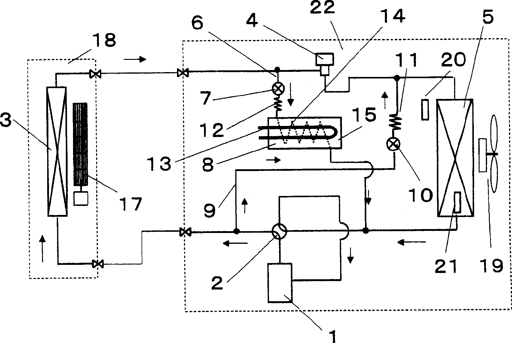
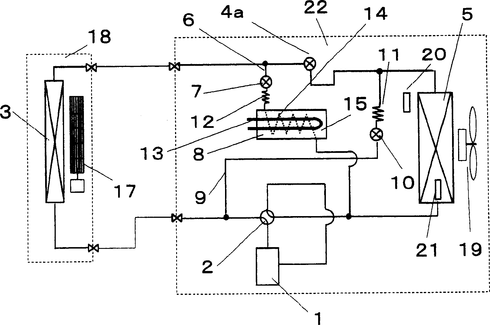
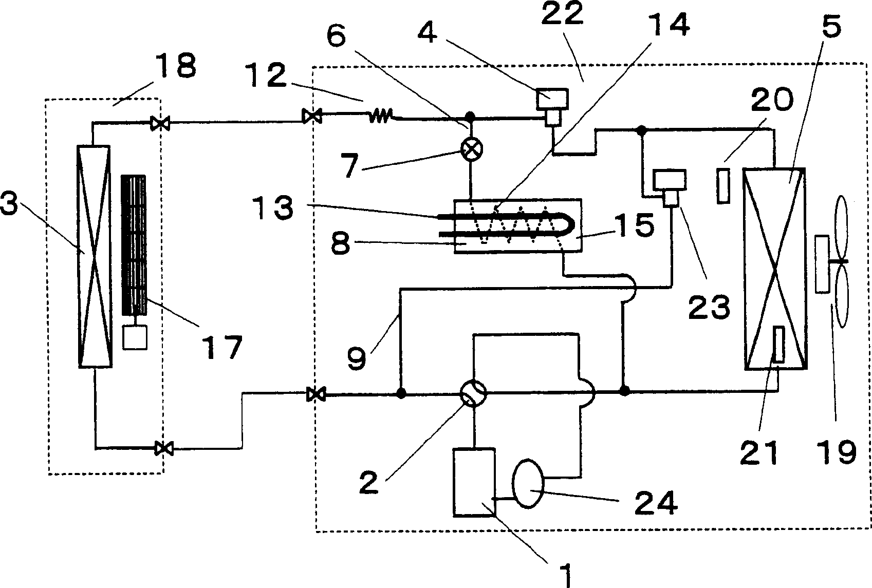
[0045] figure 1 It is a block diagram of the air-conditioning apparatus of 1st Embodiment of this invention. In the same figure, the outdoor unit 22 is equipped with: a compressor 1, a four-way valve 2, a pressure reducer 4, an outdoor side heat exchanger 5, a first bypass circuit 6, a two-way valve for refrigerant heating 7, a refrigerant Heater 8, second bypass circuit 9, two-way valve 10 for defrosting of the second bypass circuit, pressure reducer 11 of the second bypass circuit, two-way valve 7 of the first bypass circuit, first bypass The pressure reducer 12, the refrigerant heating heat source 13, the refrigerant passage pipe 14, the heat storage part 15, the outdoor air blower 19, the outdoor temperature detection part 20, and the outdoor heat exchanger temperature detection part 21 pass through the circuit.

[0046] The indoor unit 18 is equipped with an indoor heat exchanger 3 and an indoor blower 17 . The pressure reducer 4 here may be an electromagnetic expansio...


PUM


Abstract

This invention provides an air-conditioner that continues a heating operation while performing a defrosting operation. A first bypass circuit 6 is provided for connecting the portion of a heat-pump-type refrigerating cycle between an indoor heat exchanger 3 and a decompressor 4 to the suction side of a compressor 1. The first bypass valve 6 is provided with a two-way valve 7 and a refrigerant heater 8. Further, a second bypass circuit 9 is provided for connecting the portion between a four-way valve 2 and the indoor heat exchanger 3 to the portion between the decompressor 4 and an outdoor heat exchanger 5. The second bypass circuit 9 is provided with a defrosting two-way valve 10. To defrost the outdoor heat exchanger 5, the decompressor 4 and the defrosting two-way valve 10 are closed according to outside air temperature and a fan 19 is rotated to perform a first defrosting operation. When the temperature detected by the temperature means of the outdoor heat exchanger is less than a predetermined value while the first defrosting operation is within a preset period of time, the two-way valve of the second bypass circuit is opened and an outdoor fan is stopped to perform a second defrosting operation.

Description

technical field [0001] The present invention relates to an air conditioner capable of performing a defrosting operation for removing frost adhering to an outdoor heat exchanger while continuing heating during heating operation by heat pump operation. Background technique [0002] In the past, the defrosting method of this kind of heat pump type air conditioner usually adopts the defrosting method of switching the four-way valve so that the refrigerant in the refrigeration cycle flows in the opposite direction. [0003] That is, in the defrosting operation, the refrigerant flow direction is the same as that during cooling, and the high-temperature and high-pressure refrigerant flows to the outdoor heat exchanger to melt frost adhering to the heat exchanger. [0004] In this defrosting method, there is a basic problem that the temperature of the room inside the room is lowered and a feeling of cool air is felt because the heat exchanger on the inside of the room becomes an eva...

Claims


Application Information

Patent Timeline
Patent Type & Authority Applications(China)
IPC IPC(8): F25B47/02F25B13/00
Inventor 内田好昭西原义和吉椿纪史
Owner PANASONIC CORP
Learn More