
Coated wafer level camera modules and associated methods

A wafer-level, coating technology, applied in radiation control devices, components of color TVs, components of TV systems, etc., can solve the problems of complex production process, increase the overall weight and size of the device, and reduce the The effect of production complexity, size and/or weight reduction

Active Publication Date: 2007-02-21
OMNIVISION TECH INC
View PDF0 Cites 7 Cited by
  • Summary
  • Abstract
  • Description
  • Claims
  • Application Information

AI Technical Summary

Problems solved by technology

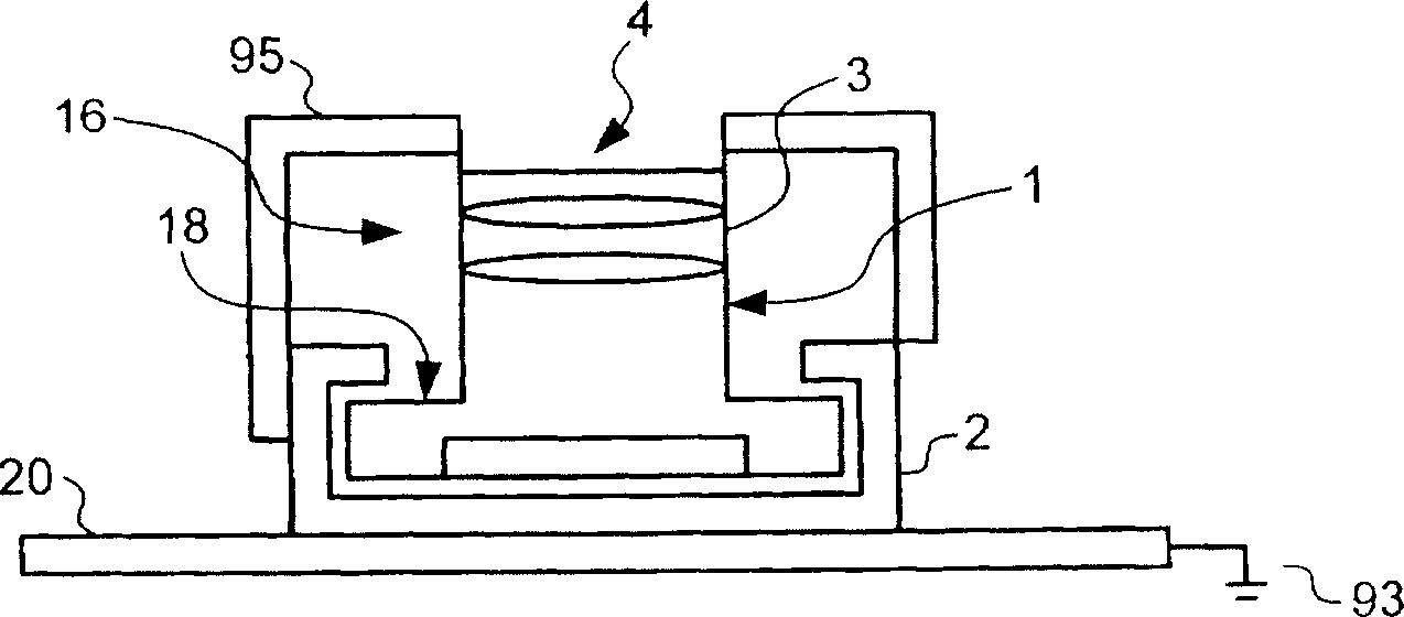
[0004] exist figure 1 During the production of the assembly shown, the use of socket 2 as well as the metal box 95 would complicate the production process
Moreover, metal box 95 and slot 2 will increase the overall weight and size of the device, which is undesirable

Method used


Image

  • Coated wafer level camera modules and associated methods
  • Coated wafer level camera modules and associated methods
  • Coated wafer level camera modules and associated methods

Examples


Embodiment Construction

[0019] In the following description, numerous specific details are provided in order to provide a thorough understanding of specific embodiments of the invention. However, one skilled in the art will recognize that the invention can be practiced without one or more of these specific details, or that the invention can be practiced without other methods, elements, materials, operations, etc. . In addition, well-known structures and operations are not shown or described in detail in order to clearly describe the various embodiments of the present invention.

[0020] In the description of the present invention, when referring to "an embodiment" or "a certain embodiment", it means that the specific features, structures or characteristics described in this embodiment are included in at least one embodiment of the present invention. Thus, appearances of "in an embodiment" or "in a certain embodiment" in various places in the specification do not necessarily refer to all belonging to...


PUM


Abstract

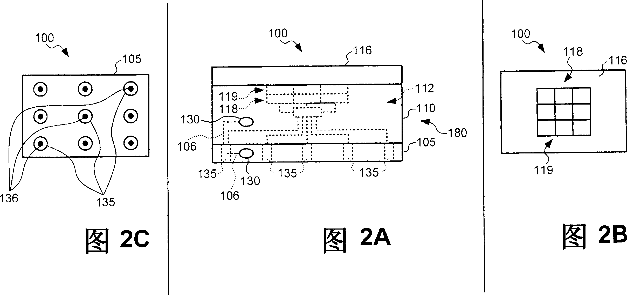
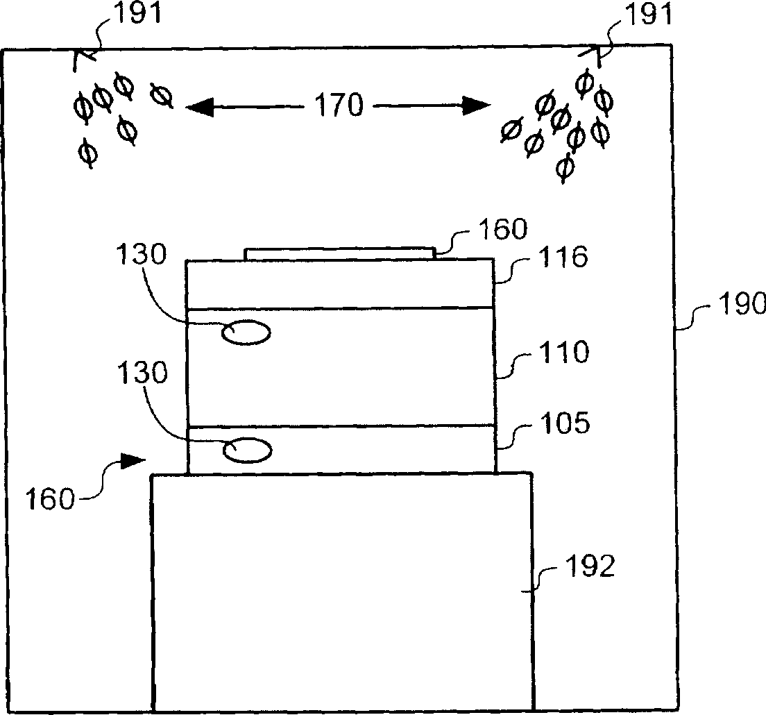
Coated wafer level camera modules and associated methods are disclosed. One aspect of the invention is directed toward a wafer level camera module that includes a die having multiple image sensor integrated circuits. The module can further include a coating covering at least a portion of the die. The coating can be configured to provide at least a partial shield against selected types of electromagnetic energy. The module can still further include multiple contacts positioned to electrically couple the integrated circuits to a support. In certain embodiments, the selected types of electromagnetic energy can include one or more selected frequencies of light.

Description

technical field [0001] The present invention relates to a coated wafer-level camera module and its corresponding method of manufacture. Background technique [0002] Image sensors have become ubiquitous, and they are widely used in digital cameras, cellular phones, security cameras, medical equipment, automobiles, and other applications. The technology of manufacturing image sensors, especially CMOS (Complementary Metal Oxide Semiconductor) image sensors continues to develop rapidly. For example, the requirements of high resolution and low power consumption promote the further miniaturization and integration of image sensors. [0003] Many microelectrophotographic modules require shielding from various forms of electromagnetic energy. Current systems use a grounded metal box placed above the camera module to shield against electromagnetic radiation. E.g, figure 1 is a prior art partial cross-sectional view showing the camera module 1 mounted on the printed circuit board ...

Claims


Application Information

Patent Timeline
Patent Type & Authority Applications(China)
IPC IPC(8): H01L27/146H01L23/488H01L23/552H01L21/60H04N5/225
CPCH04N5/2253H01L27/14687H01L27/14632H01L2924/0002H01L27/14618H04N23/54H01L2924/00
Inventor 杰瑞·希尔图宁
Owner OMNIVISION TECH INC
Learn More