
(111) silicon based micro mechanical acceleration sensor and its manufacture

An acceleration sensor and micro-machine technology, applied in the measurement of acceleration, velocity/acceleration/impact measurement, instruments, etc., can solve the problems of increased process cost, high stress, complex process, etc., to reduce the difficulty of the manufacturing process, reduce the manufacturing cost, The effect of ensuring symmetry

Inactive Publication Date: 2007-02-28
温州尚品科技有限公司
View PDF4 Cites 14 Cited by
  • Summary
  • Abstract
  • Description
  • Claims
  • Application Information

AI Technical Summary

Benefits of technology

This patented technology describes different embodiments for improving the design of accelerometer systems that include both sensitive elements made from silicon alone and more advanced materials like glassy plasma blocks. These improvements make them easier to produce while maintaining their desired properties. They also allow for precise measurement without any misalignment during assembly, reducing costs associated therewith. Overall these technical results help create better quality products for various applications including oil drilling operations.

Problems solved by technology

This technical problem addressed in this patents relates to complex processes involved during producing high performance MEMS sensors used in various industries such as defense industry or civil engineering. Existing techniques involve opening loops and closing loops, which require precise alignment and assembly steps, leading to increased costs and instabilities over time. Therefore, new solutions must overcome issues associated with existing technologies like those described earlier.

Method used


Image

  • (111) silicon based micro mechanical acceleration sensor and its manufacture
  • (111) silicon based micro mechanical acceleration sensor and its manufacture
  • (111) silicon based micro mechanical acceleration sensor and its manufacture

Examples


Embodiment Construction

[0085] The structural features and manufacturing process of the present invention are further explained below in conjunction with the accompanying drawings.

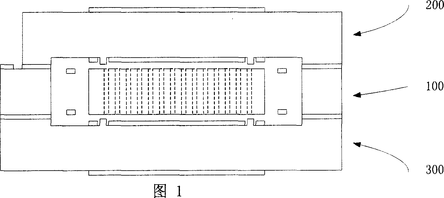
[0086] The present invention provides a (111) silicon-based micromechanical acceleration sensor and a manufacturing method thereof. The sensor is composed of a (111) single crystal silicon substrate 100, an upper substrate 200 and a lower substrate 300 each, and

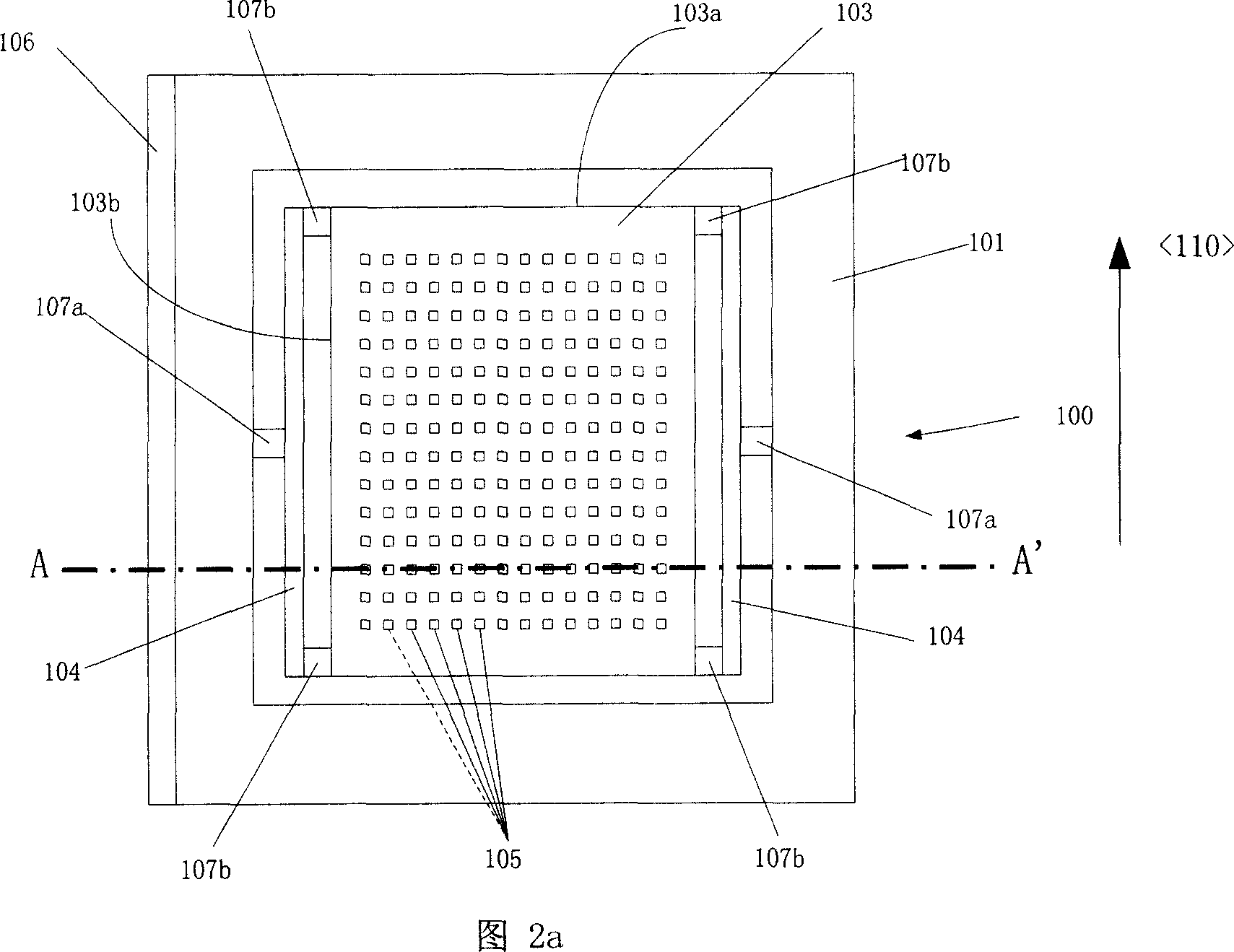
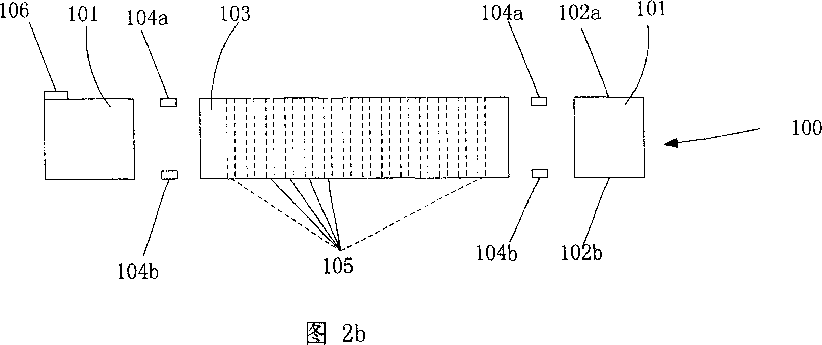
[0087] a) On the (111) silicon substrate 100 there are inertial mass blocks 103, at least a pair of elastic suspension beams 104, and a frame; the elastic suspension beams 104 are symmetrical up and down relative to the (111) silicon substrate 100, and one end of each elastic suspension beam 104 is connected on the inertial mass block 103, and the other end is connected to the frame 101;

[0088] b) The inertial mass 103 can move perpendicular to the (111) direction of the surface of the silicon substrate 100 under the support of the elastic cantilever beam 104...


PUM

PropertyMeasurementUnit
Thicknessaaaaaaaaaa

Abstract

The invention relates to a micro mechanical acceleration sensor based on (111) silicon, and relative production, wherein said sensor is formed by one (111) single crystal silicon substrate and upper and lower substrates; the inertia quality of silicon substrate via at least one couple of flexible suspension beams of one substrate is connected to the fixed frame, to vertically move relative to the substrate via external acceleration, and change the capacitor between the plate electrodes of upper and lower substrates, to detect external acceleration. Said flexible suspension beams are symmetry relative to the (111) silicon substrate, while its size control and production are based on silicon chemical aeolotropism corrosion and height-depth-width ratio dry method etching technique; the (111) silicon substrate and upper and lower substrates are bonded by align bonds. The inventive sensor can realize closed detection, with controllable technique, high accuracy and the application with multi-axle integration.

Description


Claims


Application Information

Patent Timeline
Owner 温州尚品科技有限公司
Learn More