High frequency discharge excited gas laser oscillator

A gas laser and high-frequency discharge technology, applied in lasers, laser parts, electrical components, etc., can solve the problems of rising prices, complicated device structures, and accuracy depends on the performance of detectors, achieving a simple structure and improving laser output. Effect

Inactive Publication Date: 2007-02-28
FANUC LTD
View PDF5 Cites 3 Cited by
  • Summary
  • Abstract
  • Description
  • Claims
  • Application Information

AI Technical Summary

Problems solved by technology

Therefore, the pulse output depends on the accuracy of the conversion table, and there must be a limit to make the pulse output close to the upper limit.
In addition, the accuracy of the pulse output depends on the performance of the d...

Method used


Image

  • High frequency discharge excited gas laser oscillator
  • High frequency discharge excited gas laser oscillator
  • High frequency discharge excited gas laser oscillator

Examples


no. 1 approach

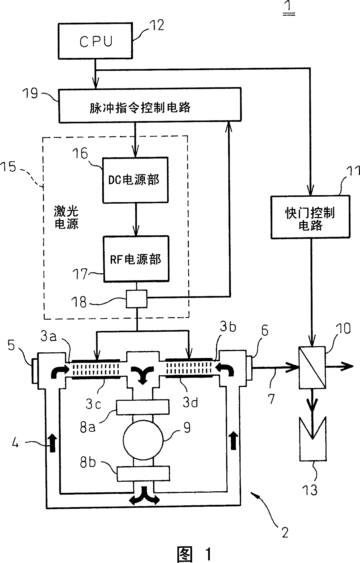
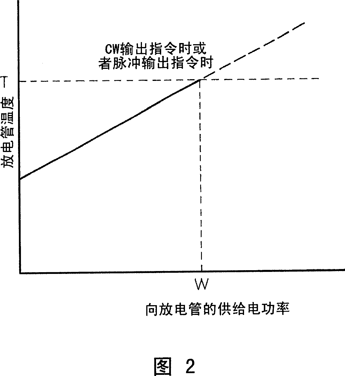
[0023] As shown in FIG. 1 , the high-frequency discharge-excited gas laser oscillator 1 of the present embodiment has an oscillator body 2, a laser power supply 15 for supplying electric power to the discharge tubes 3a and 3b of the discharge-excited laser 7, and a laser power supply 15 for detecting discharge from the laser power supply 15. The RF power detection circuit (power detection unit) 18 for supplying electric power of the tubes 3a, 3b, the pulse command control circuit (command control unit) 19 for controlling the pulse command value to the discharge tubes 3a, 3b, according to the temperature of the discharge tube and the value of the supplied power Find the allowable upper limit value W of the electric power supply (refer to FIG. 2 ), compare the allowable upper limit value W with the detected actual electric power supply, and control the pulse output command value to the discharge tubes 3a and 3b so that the actual electric power supply Do not exceed the allowable ...


PUM


Abstract

A high-frequency discharge excited gas laser oscillator receiving power from a laser power supply controlled by a pulse command, the high-frequency discharge excited gas laser oscillator provided with a power detecting section for detecting supply power from the laser power supply to a discharge tube and a pulse command control circuit positioned at an upstream side of the laser power supply, comparing an allowable upper limit value (W) of supply power found from a relationship between a discharge tube temperature and supply power and an actual supply power detected by the power detecting section, stopping the pulse command value to the discharge tube when the supply power is higher than the allowable upper limit value, and setting a pulse command value based on the allowable upper limit value.

Description

technical field [0001] The present invention relates to a high-frequency discharge-excited gas laser oscillator suitable for a laser processing machine, which supplies electric power to a discharge tube from a laser power source controlled by pulse commands. Background technique [0002] Generally, in laser processing using a high-frequency discharge-excited gas laser oscillator, when high-quality drilling processing or stable cutting processing is performed, processing is performed using a pulse output laser controlled by a pulse command. This is because, as can be seen from the relationship between the discharge tube temperature and the peak output command value shown in FIG. 4 , the peak output value can be made higher at the time of the pulse output command than at the time of the CW output command. That is, it is due to the following reason: the temperature T at which the discharge tube breaks increases with the increase of the peak output value, but compared with the a...

Claims


Application Information

Patent Timeline
IPC IPC(8): H01S3/00H01S3/097
CPCH01S3/097H01S3/073H01S3/036H01S3/134H01S3/10069
Inventor 江川明安藤稔池本肇
Owner FANUC LTD
Why Eureka
Try Eureka