Driving device of sliding vehicle

A transmission device and scooter technology, which is applied in the direction of motor vehicles, bicycles, vehicle parts, etc., can solve the problems of complex transmission structure and heavy vehicle body weight.

Inactive Publication Date: 2007-03-07
梁仁宇
View PDF0 Cites 5 Cited by
  • Summary
  • Abstract
  • Description
  • Claims
  • Application Information

AI Technical Summary

Problems solved by technology

However, in the past, this type of skateboard was heavy because of its complex transmission structure. However, considering outdoor use, it should be based on a simple structure and a light body.

Method used


Image

  • Driving device of sliding vehicle
  • Driving device of sliding vehicle
  • Driving device of sliding vehicle

Examples


Embodiment Construction

[0041] In order for those skilled in the art to further understand the features and technical content of the present invention, please refer to the following detailed description and accompanying drawings of the present invention. The accompanying drawings are provided for reference and illustration only, and are not intended to limit the present invention.

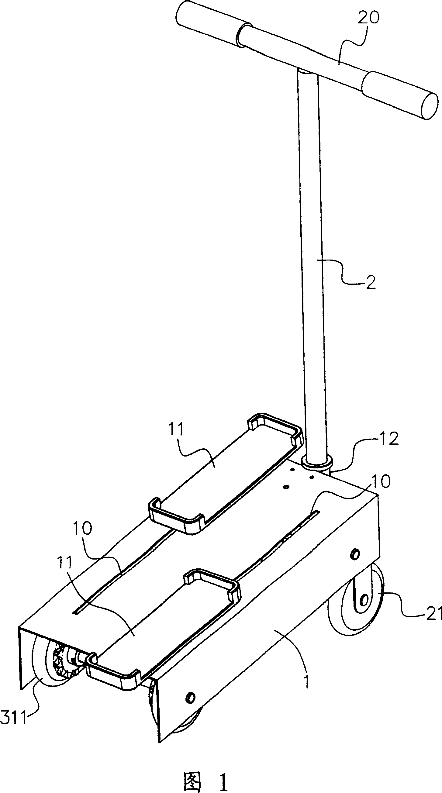
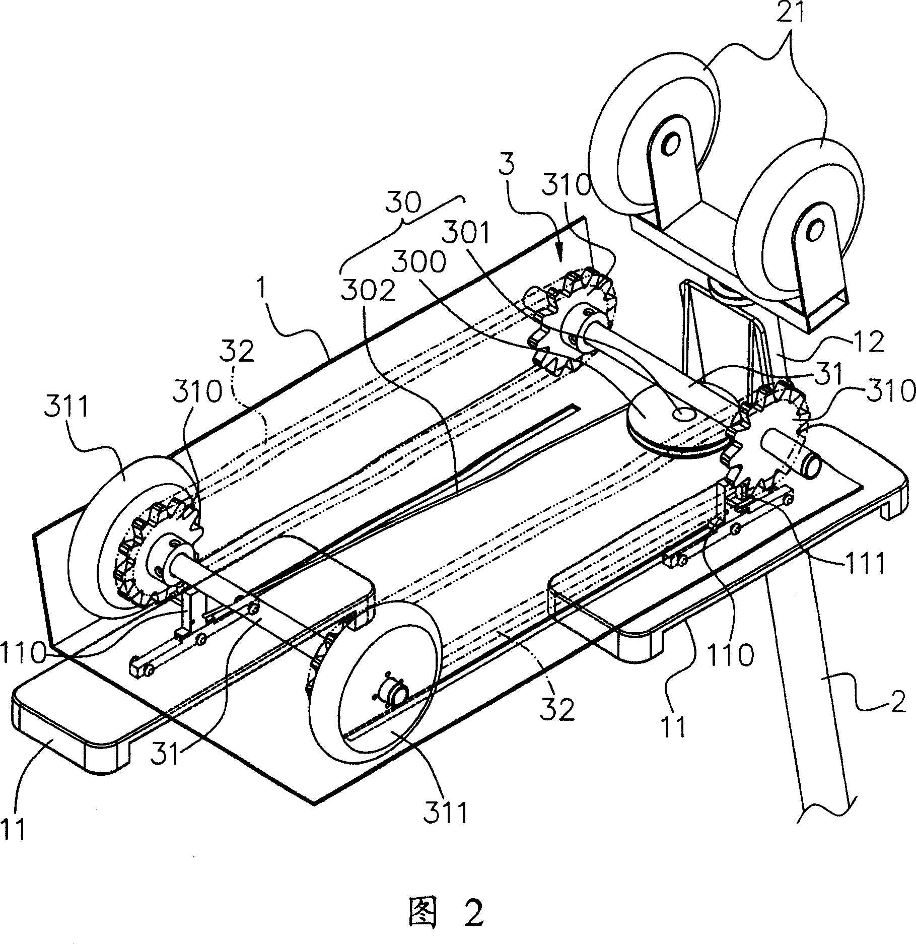
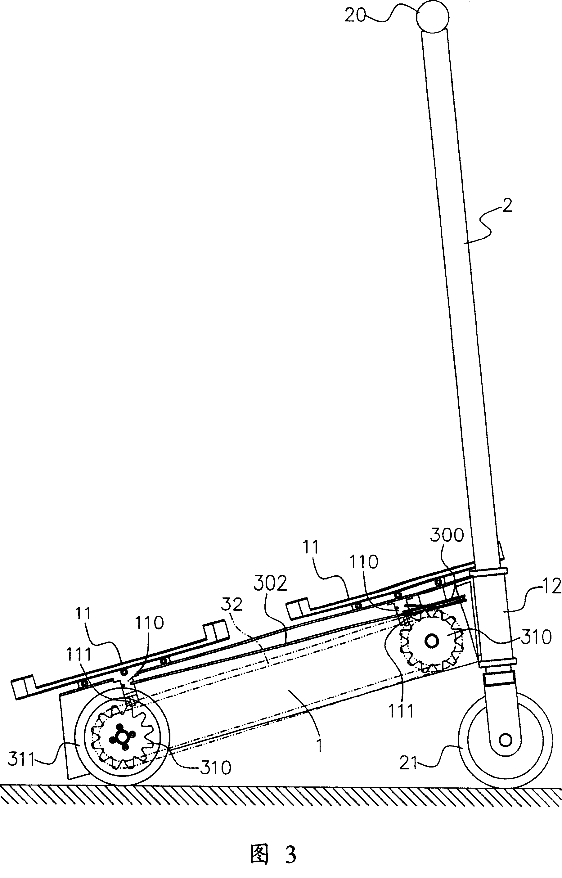
[0042] FIG. 1 , FIG. 2 and FIG. 3 are a three-dimensional appearance view of the present invention, a three-dimensional appearance view from another perspective, and a schematic side view, respectively. The present invention provides a scooter and its transmission device. The scooter includes a frame 1, a handlebar 2 and a transmission device 3; wherein:

[0043] The vehicle frame 1 is a substantially "ㄇ"-shaped frame body, and two mutually parallel rails 10 are arranged on its top surface. Pedals 11 are slidably disposed on the two rails 10 , connecting portions 110 are respectively provided on the bottom surfaces of the...


PUM


Abstract

A sliding walking bike and its drive system comprise of a frame, steer, immobile block mechanism, two driving shaft lever and two drive chains; this immobile block has a rotating part connected to the frame through a pivot, a traction component circling around the rotating part with its both ends connect to two pedals of the frame, and two driving shaft lever whose both ends has gears that connected with drive shaft lever through a ratchet, and which is equipped at the front and rear ends of the frame respectively; two drive chains mate with gears at both ends of two drive shaft lever to drive separately for the juncture of the frame and two pedals.

Description

technical field [0001] The invention relates to a slide car and its transmission device, in particular to a slide car and its transmission device using the pulley block principle as the slide transmission. Background technique [0002] In order to achieve the purpose of running and fitness, traditional products related to running and fitness, such as treadmills, are mostly used for indoor fitness and cannot be used outdoors. Therefore, there are patents such as "the structure of running scooters" and related products such as scooters. However, in the past, this type of slide car was heavy because of its complex transmission structure, but considering outdoor use, it should be based on a simple structure and a light body. [0003] In view of this, the present inventor artificially improves and solves the defects in the above-mentioned prior art. After painstaking research and application of theories, he finally proposes a reasonable design and effectively improves the above-m...

Claims


Application Information

Patent Timeline
Patent Type & Authority Applications(China)
IPC IPC(8): B62M1/00B62K17/00
Inventor 梁仁宇
Owner 梁仁宇
Why Eureka
Try Eureka