Eccentric flow guiding valve controlled speed adjusting type hydrokinetic coupoler

A hydraulic coupling and diversion valve technology, which is applied to fluid transmission devices, belts/chains/gears, mechanical equipment, etc., to reduce weight, reduce oil filling, and enhance safety

Inactive Publication Date: 2007-03-07
上海交大南洋机电科技有限公司
View PDF1 Cites 7 Cited by
  • Summary
  • Abstract
  • Description
  • Claims
  • Application Information

AI Technical Summary

Problems solved by technology

The patent number is ZL03267197.0, and the invention patent named "Clutch-type speed-regulating hydraulic coupling" is based on the original speed-regulating hydraulic coupling. The guide tube and the guide cavity are not canceled

Method used


Image

  • Eccentric flow guiding valve controlled speed adjusting type hydrokinetic coupoler
  • Eccentric flow guiding valve controlled speed adjusting type hydrokinetic coupoler

Examples


Embodiment Construction

[0021] The specific implementation of the present invention will be further described below in conjunction with the accompanying drawings.

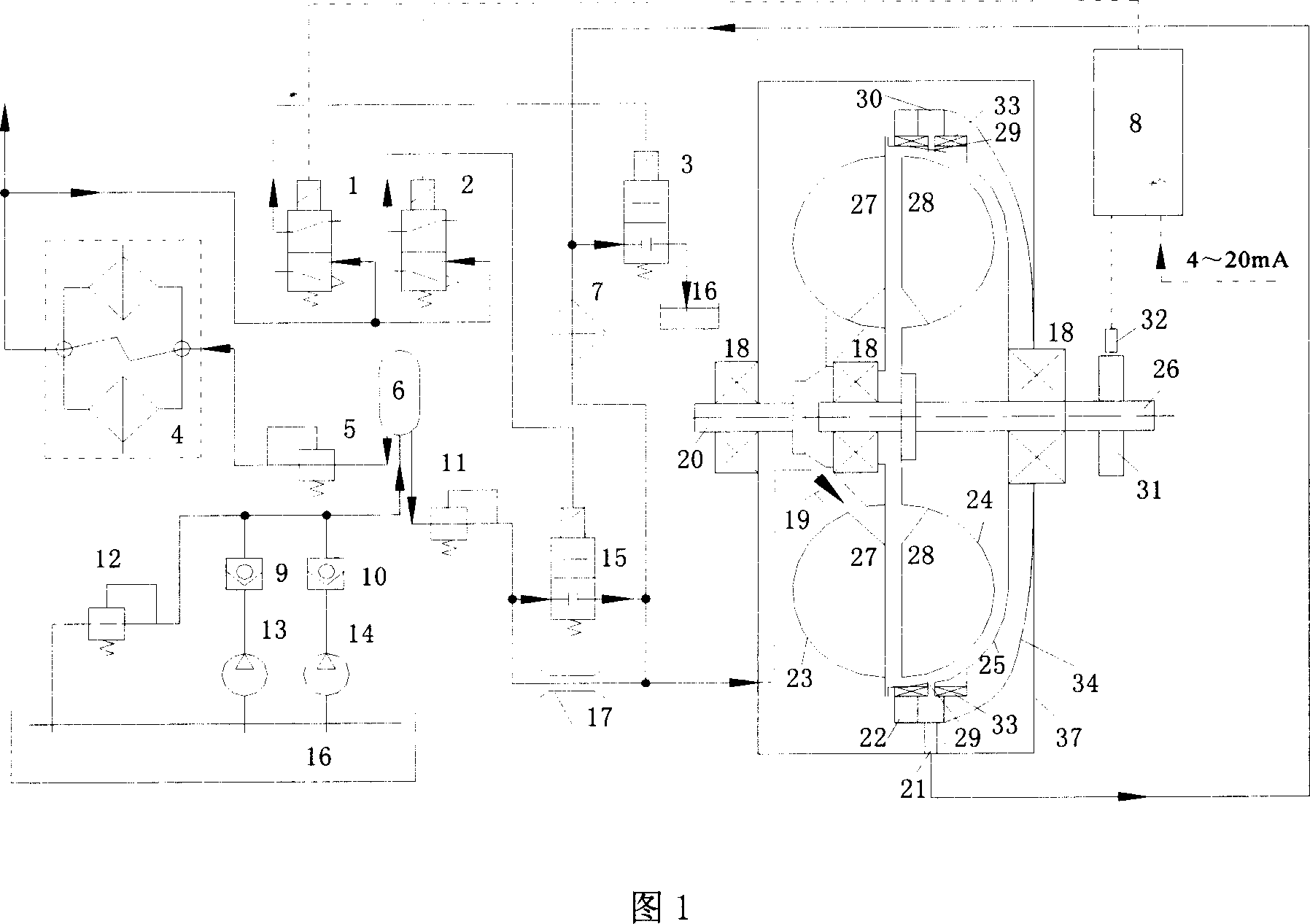
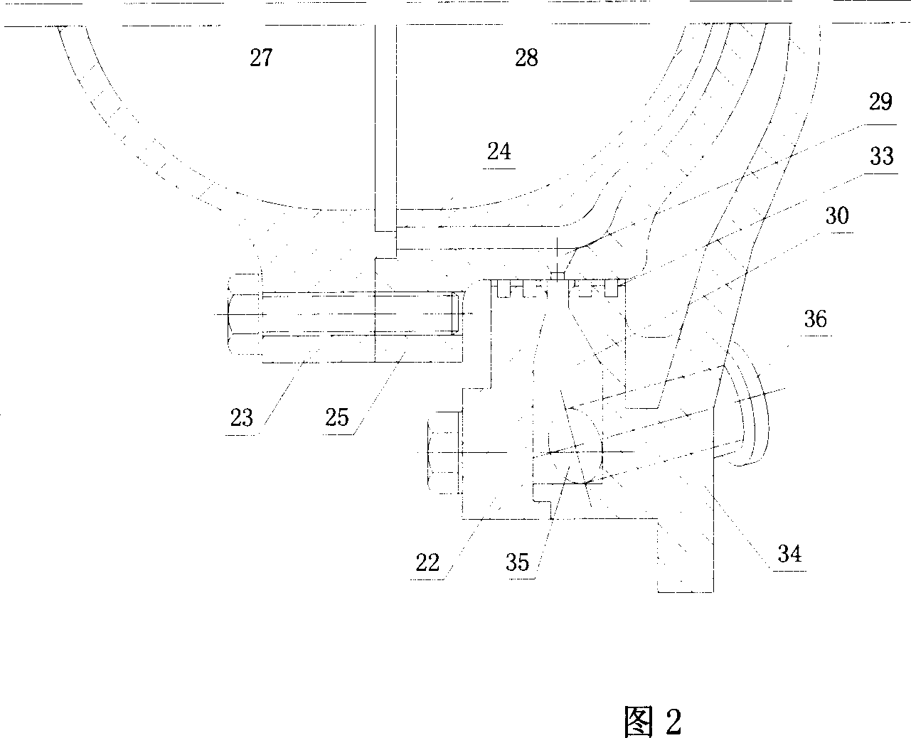
[0022] As shown in Figure 1 and Figure 2: the present invention includes A pilot valve 1, B pilot valve 2, A hydraulic control valve 3, duplex filter 4, A pressure reducing valve 5, pressure accumulator 6, cooler 7, control Device 8, A one-way valve 9, B one-way valve 10, B pressure reducing valve 11, overflow valve 12, A electric pump 13, B electric pump 14, B hydraulic control valve 15, oil pool 16, throttle orifice 17. Bearing 18, oil inlet connecting pipe 19, drive shaft 20, oil outlet connecting pipe 21, centrifugal shroud 22, pump wheel 23, turbine wheel 24, back wheel 25, driven shaft 26, pump wheel cavity 27, Turbine cavity 28, centrifugal diversion hole 29, centrifugal diversion groove 30, speed measuring gear 31, speed sensor 32, oil seal 33, end cover 34, passage hole 35, flange 36, box body 37.

[0023]The pump wheel 23 is fl...


PUM


Abstract

This invention relates to eccentric flow guide valve control speed adjusting hydraulic coupler, which comprises the following parts: two guide valves, two hydraulic control valve, two release valves, two electrical pumps, filter, storage device, cooling device, controller, two single valves, overflow valve, oil pool, flow saving hole board, eccentric guide cover, eccentric hole guide, eccentric guide tank, speed test gear, speed sensor, oil sealing, top cover and channel hole.

Description

technical field [0001] The invention relates to a speed-regulating hydraulic coupling, in particular to a method of drawing out the working oil in the working chamber of the coupler for cooling by using the principle of centrifugal flow diversion, and controlling the filling of the working oil of the speed-regulating hydraulic coupling through a valve. The utility model relates to a centrifugal diversion valve-controlled speed-regulating hydraulic coupling for adjusting the output rotational speed, which belongs to the technical field of energy saving and hydraulic transmission. Background technique [0002] At present, there are many traditional speed-regulating hydraulic couplings, and their common feature is that a certain amount of working oil is filled in the working chamber of the hydraulic coupling, and the pump wheel obtains mechanical energy from the prime mover, converts it into liquid energy, flows to the turbine and Make it rotate, the turbine converts the liquid...

Claims


Application Information

Patent Timeline
Patent Type & Authority Applications(China)
IPC IPC(8): F16H41/00F16H41/24
Inventor 黄刘琦邓真全庞之洋庄建英
Owner 上海交大南洋机电科技有限公司
Why Eureka
Try Eureka