Rotary valve type sonic blowing ash device

A technology of sonic soot blower and rotary valve, which is applied in the direction of sound-emitting devices, instruments, and combustion product treatment. It can solve the problems of inability to rotate at high speed, jamming of impurities, and failure to work, and achieve long-term stable operation, long service life, The effect of simple structure

A technology of sonic soot blower and rotary valve, which is applied in the direction of sound-emitting devices, instruments, and combustion product treatment. It can solve the problems of inability to rotate at high speed, jamming of impurities, and failure to work, and achieve long-term stable operation, long service life, The effect of simple structure

CN1928434AInactive Publication Date: 2007-03-14่‚้“้™ +1

Image

  • Rotary valve type sonic blowing ash device
  • Rotary valve type sonic blowing ash device

Examples


Embodiment Construction

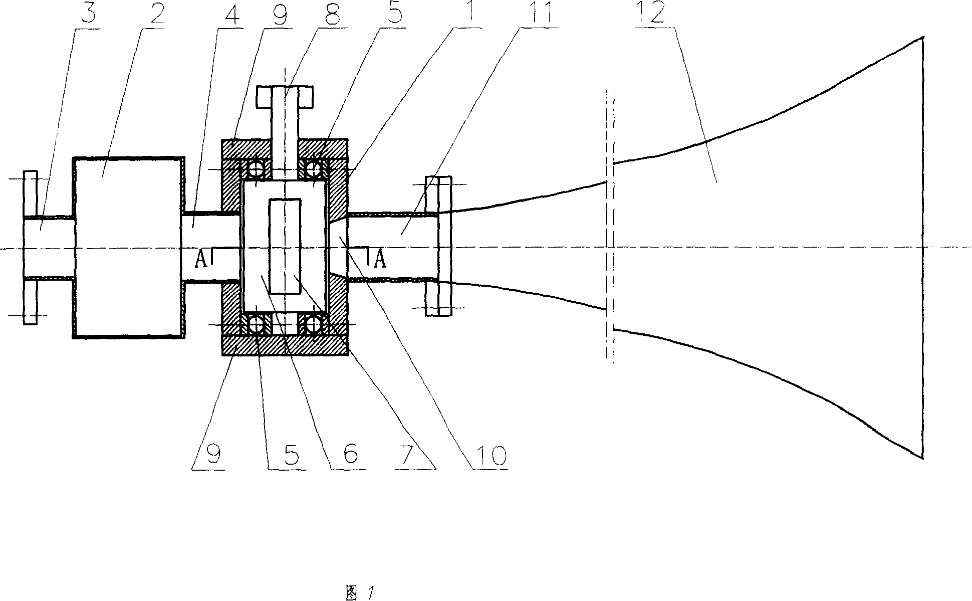
[0009] The working principle of the present invention is as follows:

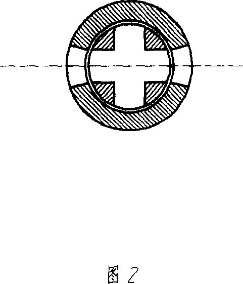
[0010] The high-pressure airflow enters the stator 1 from the air inlet pipe 3 through the air chamber 2. Since the rotor 6 is placed in the stator 1, the rotor 6 is supported by the bearing 5. In this way, the rotor 6 can be driven by the rotor shaft 8 to rotate at a high speed in the stator 1. The rotor 6 is provided with a square or rectangular hole or slot 7, and the cross section of the spout 10 is circular. According to the principle of kinematics, the relative motion of the two holes intersects, and the flow area of โ€‹โ€‹the spout 10 changes according to the sine law. In this way, the change of the air flow also changes according to the sine law, that is, the high pressure air flow is modulated into a pressure pulse that changes according to a sine wave, so that the air flow ejected from the nozzle 10 is intermittently on and off, and becomes a pulse state. The pulse frequency is generally 100-300kz, an...


PUM


Abstract

The invention discloses an acoustic soot blower with rotary valve, belonging soot-blowing equipment. By setting groove or hole on the rotor, rotor rotating in the stator and mounting with inlet pipe, air room, jet nozzle and acoustic-formed device, the blower can make air flow with high pressure converse sound wave with heavy power. By sound wave blowing soot, there is not easy to jam between every part; because of the structure without films, the film damage generated by high-frequency intense vibration is avoided, which affects the normal work of soot blower. It is provided with simple structure and long service life. It can be long run in hard circumstance such as boiler.

Description

technical field [0001] The invention relates to an ash removal device, in particular to a rotary valve type sonic sootblower which uses a rotary valve to generate sound waves and uses the sound waves to remove ash. Background technique [0002] When all kinds of boilers are running, there is ash accumulation on the heat exchange surface. If they are not removed in time, the heat exchange efficiency of the boiler will be affected, and the safe operation of the boiler will be endangered when the ash accumulation is serious. The traditional soot blowing is to use steam soot blowing. The steam soot blower used in this soot blowing method has a high failure rate, large energy consumption, poor soot blowing effect, damage to the boiler, and a dead angle for soot blowing. The use of sonic soot blowing is to send high-power sound waves into the furnace to generate a sound field with high sound pressure level in the furnace. Fatigue falls off and is carried away with the flue gas f...

Claims


Application Information

Patent Timeline
14 Mar 2007
Publication
CN1928434A
IPC
F23J3/00; G10K9/02
Inventors
ๅพ่ดค้‡‘; ่‚้“้™