Electron source and surface light source employing same

A technology of electron source and surface light source, which is applied in the field of electron source, can solve problems such as unfavorable environment and non-compliance with environmental protection requirements, and achieve the effects of high ionization rate, improved emission rate, and high brightness

Inactive Publication Date: 2010-08-11
HONG FU JIN PRECISION IND (SHENZHEN) CO LTD +1
View PDF0 Cites 0 Cited by
  • Summary
  • Abstract
  • Description
  • Claims
  • Application Information

AI Technical Summary

Problems solved by technology

However, cold cathode fluorescent lamps contain mercury, which is an extremely harmful substance to the environment and does not meet environmental protection requirements

Method used


Image

  • Electron source and surface light source employing same
  • Electron source and surface light source employing same
  • Electron source and surface light source employing same

Examples


Embodiment Construction

[0015] The present invention will be further described in detail below in conjunction with the accompanying drawings.

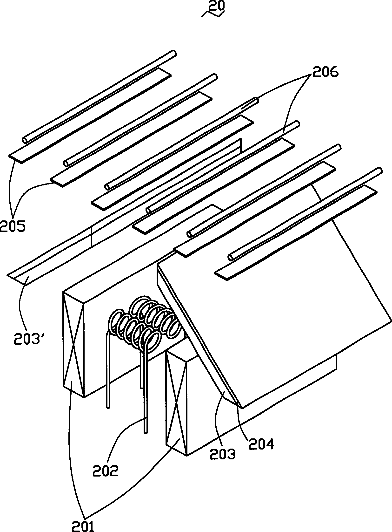
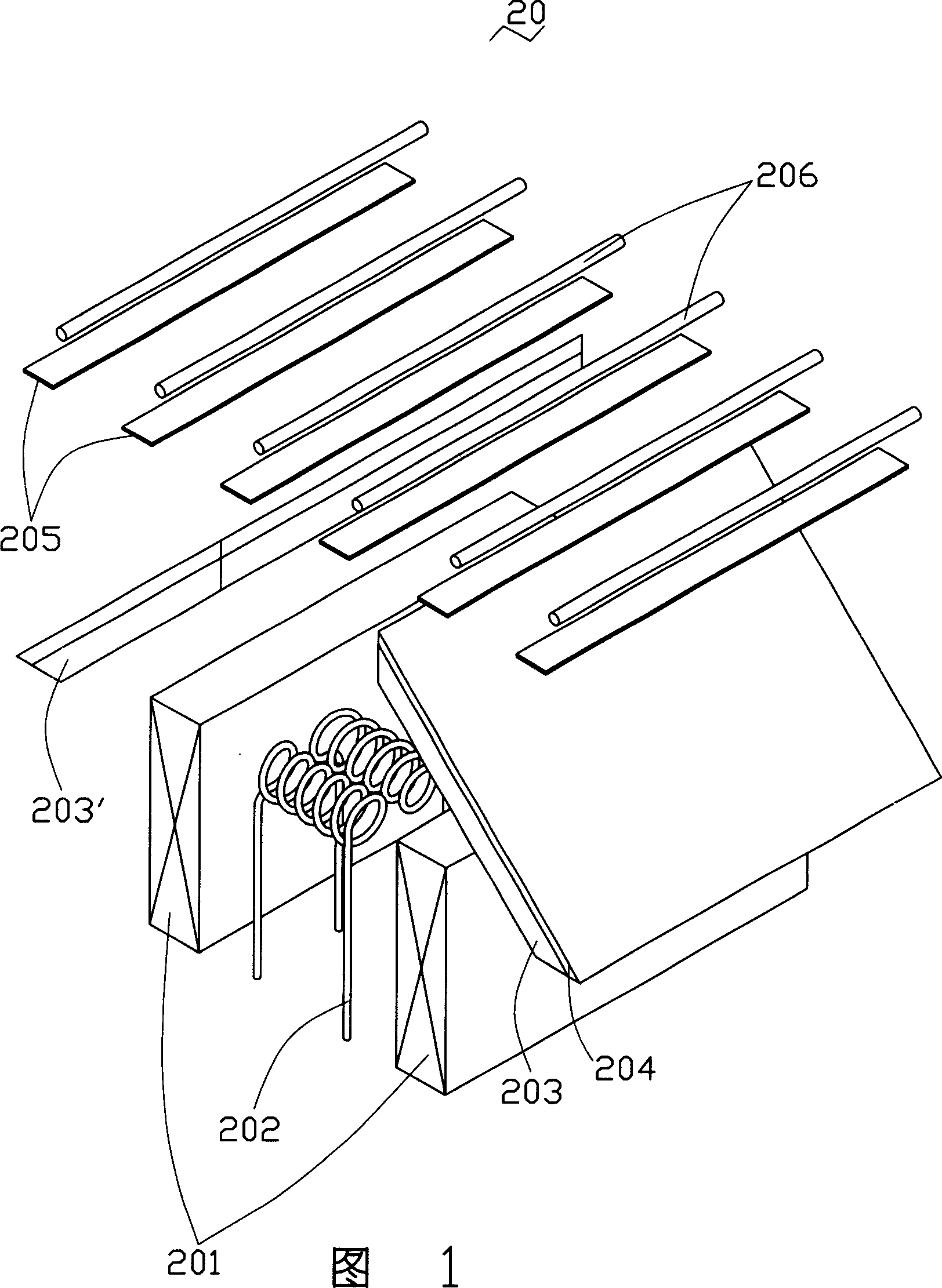
[0016] Please refer to FIG. 1 and FIG. 2 together. An electron source 20 provided by an embodiment of the present invention includes a pair of electromagnetic coils 201, a plurality of filaments 202, and two cathodes 203, 203'.

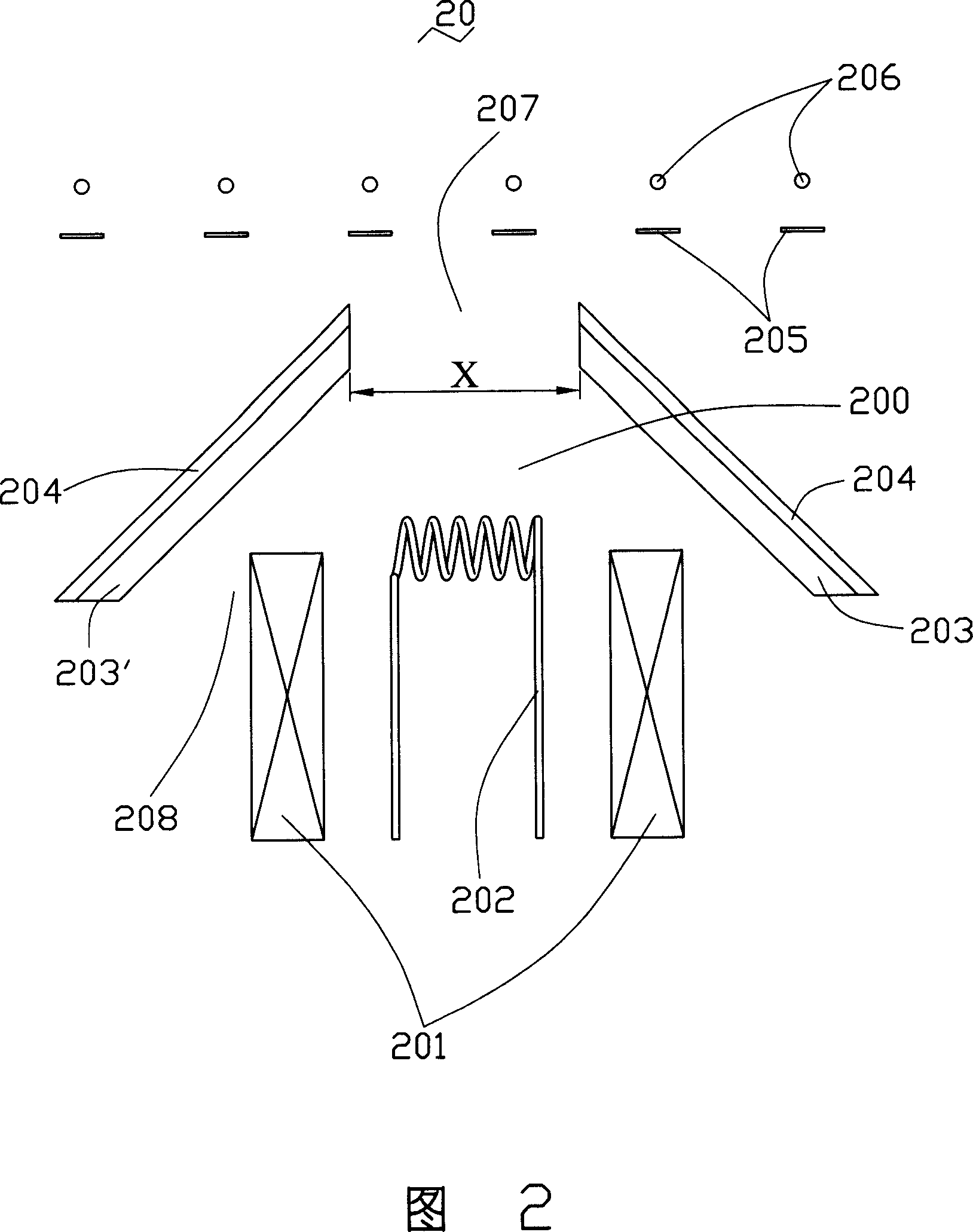
[0017] A plurality of filaments 202 is located between the pair of electromagnetic coils 201 , so that the pair of electromagnetic coils 201 heats the plurality of filaments 202 to make the plurality of filaments 202 emit electrons. The two cathodes 203, 203' are inclined relative to each other, and a cavity 200 is formed between the two cathodes 203, 203', and the cavity 200 has a first opening 207 and a second opening 208. The second opening 208 is larger than the first opening 207 , the pair of electromagnetic coils 201 and the plurality of filaments 202 are located at the second opening 208 , and the electrons emitted by the plur...


PUM

PropertyMeasurementUnit
widthaaaaaaaaaa
thicknessaaaaaaaaaa

Abstract

This invention relates to one electron source, which comprises the following parts: one magnetic coil; multiple lamp wires on coils to heating the lamp wires to send electrons; cathode set by two inclination to form one hollow chamber with one first opening and one second open relative to first larger than first open; the magnetic coil and wires locate on second open; the said multiple lamp wiressend electron from first open.

Description

【Technical field】 [0001] The invention relates to an electron source and a surface light source device using the electron source. 【Background technique】 [0002] Due to the advantages of lightness, thinness, and low power consumption, liquid crystal displays are widely used in modern information equipment such as notebook computers, mobile phones, and personal digital assistants. Since the liquid crystal itself does not have light-emitting properties, it is necessary to provide a surface light source device for it to realize the lighting display function. [0003] The surface light source device can generally be divided into two types: edge-type and direct-type according to the placement position of the light source. Generally speaking, for small and medium-sized liquid crystal displays, the edge-lit surface light source device has the advantages of light weight, thin profile, narrow frame, and low power consumption. However, with the development of science and technology,...

Claims


Application Information

Patent Timeline
Patent Type & Authority Patents(China)
IPC IPC(8): H01J3/02H01J37/06H01J61/00H01J63/00G02F1/13357
CPCH01J61/305H01J63/08
Inventor 陈杰良
Owner HONG FU JIN PRECISION IND (SHENZHEN) CO LTD
Why Eureka
Try Eureka