Focused coherent-scatter computer tomography

A technology of tomography and coherent scattering, applied in echo tomography, material analysis using radiation, nuclear radiation exploration, etc., can solve problems such as fuzzy scattering functions, and achieve the effect of avoiding the weakening of resolution anisotropy

Inactive Publication Date: 2007-03-14
KONINKLIJKE PHILIPS ELECTRONICS NV
View PDF3 Cites 1 Cited by
  • Summary
  • Abstract
  • Description
  • Claims
  • Application Information

AI Technical Summary

Problems solved by technology

The shortcoming of the angle dispersing device in conjunction with polychromatic light source is the scatter function of ambiguity, " Coherent ScatterComputer Tomography Applying a Fan-Beam Geometry (application fan-beam geometry structure) on Proc.SPIE, 2001, Vol. Coherent scatter computed tomography)” explains this

Method used


Image

  • Focused coherent-scatter computer tomography
  • Focused coherent-scatter computer tomography
  • Focused coherent-scatter computer tomography

Examples


Embodiment Construction

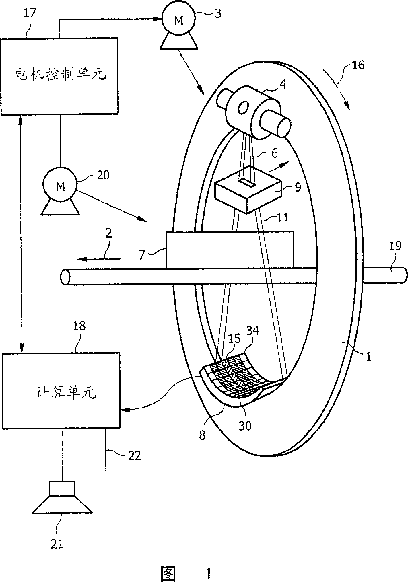
[0036] Figure 1 shows an exemplary embodiment of a computed tomography apparatus according to the invention. With reference to this exemplary embodiment, the invention will be described with respect to its application in luggage detection, eg detection of dangerous objects, such as explosives, in luggage items. However, it has to be noted that the invention is not limited to the field of baggage detection, but can also be used in other industrial or medical applications, eg bone imaging or tissue type recognition in medical applications.

[0037] The computed tomography shown in Figure 1 is a fan beam coherent-scatter computed tomography (CSCT) capable of using a magnified focal point radiation source. Additionally, in accordance with exemplary embodiments of the present invention, high-performance rotating anodes are not required to provide sufficiently high photon flux. The structure of the radiation source 4 will be explained in more detail with reference to FIG. 6 .

[0...


PUM


Abstract

Due to the provision of slit collimators an intensity of a fan beam is reduced significantly such that expensive high power x-ray tubes have to be used. According to an exemplary embodiment of the present invention, a high power tube may be used with a very long focus in combination with a focusing collimator. The tube can be a cheap fixed anode tube still with a high power of, for example, 15 kW due to the large focus. The collimator may ensure that the resolution of the reconstructed scatter function is not degraded. The illuminated slice thickness is increased which may allow for an isotropic spatial resolution.

Description

technical field [0001] The present invention relates to the field of coherent-scatter computed tomography (CSCT) in which a beam of radiation is applied to a target object. In particular, the present invention relates to a coherence-scatter computer tomography apparatus for examining a target object, a method for examining a target object with a coherence-scatter computer tomography apparatus, and a software program for controlling the computer tomography apparatus. Background technique [0002] The device described in US 4,751,722 is based on the principle of positioning the angular distribution of coherent scattered rays within an angle of 1 to 12 degrees to the beam direction. As clarified in US 4,751,722, the main part of the elastically scattered rays is concentrated within an angle of less than 12 degrees so that the photon energy is greater than 40KeV, and the scattered rays have a characteristic angle dependence with a clear maximum, the position of the characteristi...

Claims


Application Information

Patent Timeline
IPC IPC(8): A61B6/02A61B6/03G01V5/00G01N23/04
CPCA61B6/483A61B6/032
Inventor J·-P·施洛姆卡M·W·P·达加茨
Owner KONINKLIJKE PHILIPS ELECTRONICS NV
Why Eureka
Try Eureka