Supercharge Your Innovation With Domain-Expert AI Agents!

Method and device for recording marks in an information layer of an optical record carrier

A record carrier, information layer technology, applied in the direction of optical recording/reproduction/erasing methods, optical recording systems, recording including phase change results, etc., to achieve good thermal management effects

Inactive Publication Date: 2007-03-14
KONINKLIJKE PHILIPS ELECTRONICS NV
View PDF0 Cites 0 Cited by
  • Summary
  • Abstract
  • Description
  • Claims
  • Application Information

AI Technical Summary

Problems solved by technology

However, currently applied writing strategies are not yet able to maximize the benefits of these techniques

Method used


Image

  • Method and device for recording marks in an information layer of an optical record carrier
  • Method and device for recording marks in an information layer of an optical record carrier
  • Method and device for recording marks in an information layer of an optical record carrier

Examples


Embodiment Construction

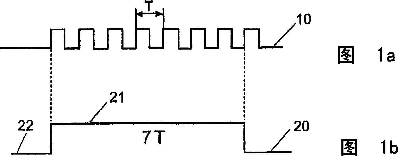
[0029]FIG. 1a shows a clock signal 10 of a reference clock with a clock period (also referred to as channel bit period) T. In FIG. Fig. 1b shows a digital data signal 20 as an example, its high level period is 21, and its low level period is 22. When recording this data signal 20, the high-level period 21 is recorded as a mark, and the length of the mark corresponds to the duration of the high-level period; the low-level period 22 is recorded as the non-writing area between the marks, that is, the interval, The length of the interval corresponds to the duration of the low period. In general, the length of a mark is substantially equal to the number of channel bit periods of the data signal multiplied by the writing speed. Therefore, in general, the mark length is represented by the number of data clock periods T when the corresponding data signal is at a high level. In the example shown in Fig. 1b, a mark with a length of 7T is recorded with a high period.

[0030] Data is ...


PUM


Abstract

The present invention relates to a method and a corresponding device for recording marks representing data in an information layer of a record carrier by irradiating the information layer by means of a pulsed radiation beam, wherein a mark is written by a sequence of write pulses, the number of write pulses of the sequence for writing a mark of length NT, T being the length of a reference clock, being determined by application of a predetermined write strategy. In order to make use of new lasers and laser drivers generating shorter laser pulses and in order to enable precise mark edge positioning leading to less bit errors it is proposed that for writing a mark of length NT either a first write strategy using (N+k) write pulses, a second write strategy using trunk(N / 2+k) write pulses, or a third write strategy using trunk(N / 3+k) write pulses, k being an integer equal to or larger than one, is applied.

Description

technical field [0001] The invention relates to a method for recording marks representing data in an information layer of a record carrier by irradiating the information layer with a pulsed radiation beam, wherein the marks are written by a sequence of write pulses for writing marks of length NT The number of write pulses in the sequence is determined by the applied predetermined write strategy, and T is the reference clock length. [0002] The invention also relates to a corresponding recording device comprising a radiation source and a control unit. Background technique [0003] In optical data storage systems data is stored on an optical record carrier such as an optical disc. Data is placed along data tracks, which typically form a spiral on the disc's substrate. Optical data storage media can be divided into three categories: read-only (ROM), recordable or write-once (R or WO), and rewritable (RW or RE). For recordable or write-once and rewritable media, the disc has...

Claims


Application Information

Patent Timeline
Patent Type & Authority Applications(China)
IPC IPC(8): G11B7/0045
CPCG11B7/00454G11B7/00456
Inventor E·R·梅恩德斯A·米杰里特斯基
Owner KONINKLIJKE PHILIPS ELECTRONICS NV
Features
  • R&D
  • Intellectual Property
  • Life Sciences
  • Materials
  • Tech Scout
  • Unparalleled Data Quality
  • Higher Quality Content
  • 60% Fewer Hallucinations
Learn More