Thermal expansion valve

A thermal expansion valve and valve hole technology, applied in the field of thermal expansion valves, can solve the problems of insufficient welding reliability, difficulty in the stable welding state of the hole on the outer wall and the head, and achieve reliable welding, prevent poor welding, and reliable welding Effect

Active Publication Date: 2007-03-21
ZHEJIANG SANHUA AUTOMOTIVE COMPONENTS CO LTD
View PDF2 Cites 19 Cited by
  • Summary
  • Abstract
  • Description
  • Claims
  • Application Information

AI Technical Summary

Problems solved by technology

[0008] According to the above, in the previous thermal expansion valve, it may be difficult to achieve a stable welding state for the welding of the hole on the outer wall and the head. Possibility of insufficient soldering reliability

Method used


Image

  • Thermal expansion valve
  • Thermal expansion valve
  • Thermal expansion valve

Examples


Embodiment 1

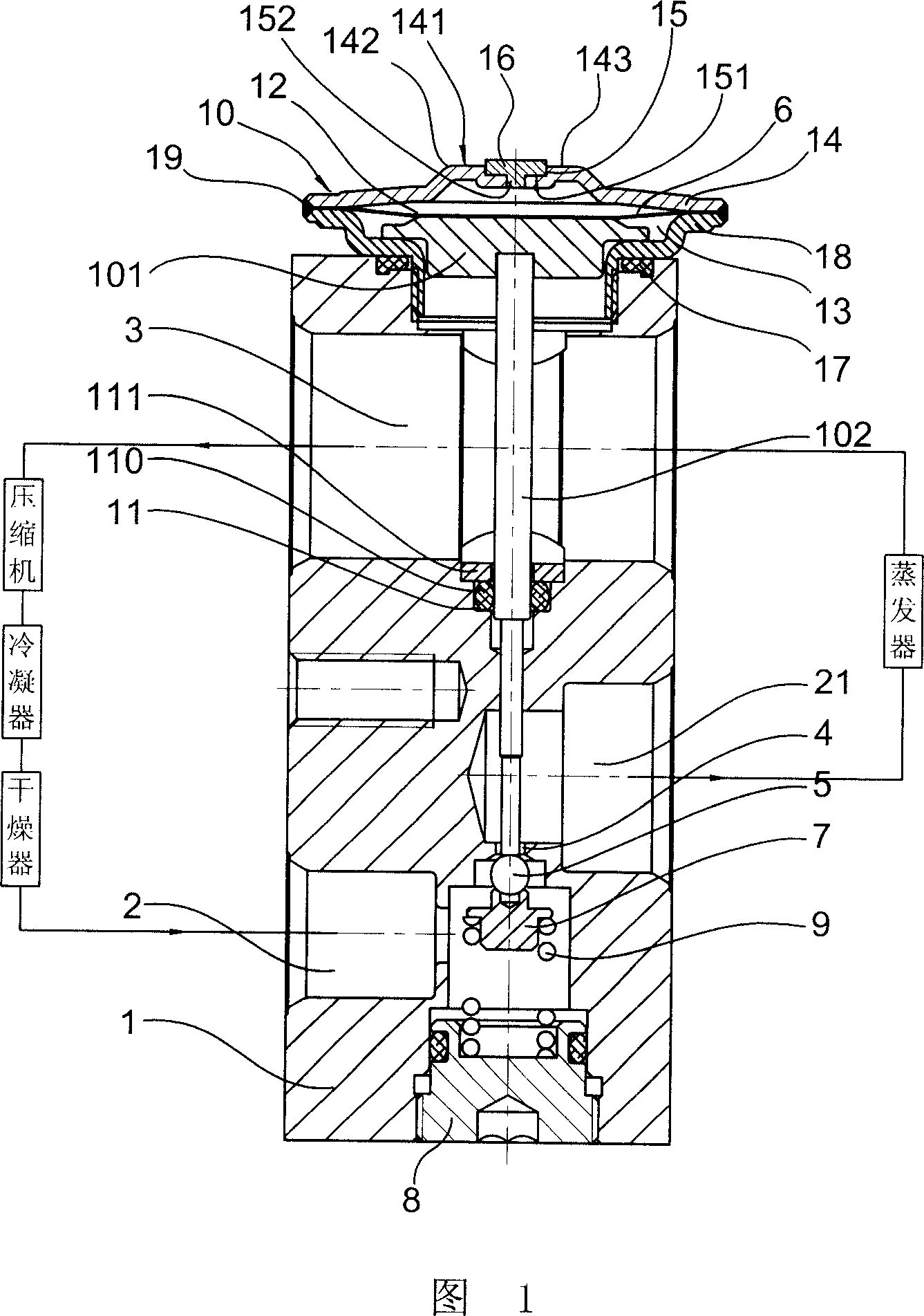
[0041] FIG. 1 depicts a thermal expansion valve installed in a refrigeration cycle in a vehicle air conditioner or the like. The valve body 1 is provided with a high-pressure refrigerant flow path 2 through which the liquid refrigerant flowing into the evaporator flows and a low-pressure refrigerant flow path 3 flowing out from the evaporator. There is a valve hole formed by a small-diameter orifice in the middle of the high-pressure refrigerant flow path 2. 4. Therefore, the liquid refrigerant flowing from the accumulator (not shown) into the high-pressure refrigerant flow path 2 passes through the valve hole 4 with a relatively small flow path area and expands adiabatically, and flows into the passage 21 . The opening portion of the valve hole 4 on the refrigerant inflow side forms a valve seat, and the opening degree of the valve hole 4 is changed by approaching or separating the spherical valve element member 5 at the valve seat. The valve core part 5 is supported by the ...

Embodiment 2

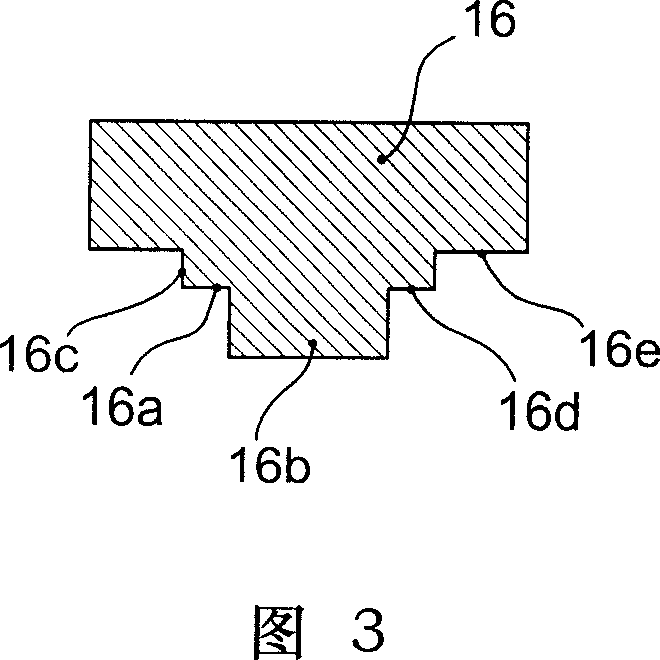
[0055] As shown in FIG. 5, a disc-shaped sealing head has a protruding portion 16a on its lower surface 16e, and the protruding portion 16a is located around the convex portion 16b formed integrally at the central part of the surface 16e of the sealing head 16, as The edge portion 6f is integrally arranged with the head. The convex part 16b and the protruding part 16a may form a separate body from the above-mentioned head.

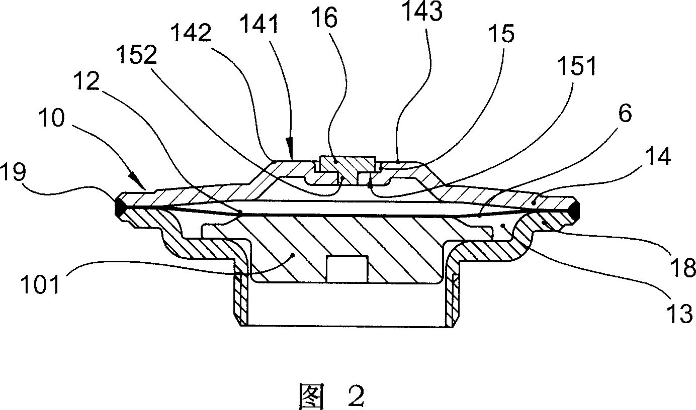
[0056] According to the above-mentioned head 16, the convex portion 16b of the head 16 is inserted into the hole formed on the bottom 151 of the recess 15 of the outer wall 14. In order to arrange the head 16 in the recess 15 and play a guiding role, the above-mentioned flange The front end 16g of 6f is in contact with the bottom of the recess 15 of the above-mentioned outer wall 14 , and the above-mentioned head 16 is combined with the outer wall 14 . Therefore, the cap 16 can be stably and firmly combined with the outer wall 14 . As a result, during th...


PUM


Abstract

The present invention relates to a thermal expansion valve. It includes the following several main portions: valve core, diaphragm, air tight chamber and seal head. Said invention also provides the concrete structure of the above-mentioned every portion and the connection mode of all the above-mentioned portions. Besides, said also provides the concrete working principle of said thermal expansion valve and its concrete application method.

Description

technical field [0001] The invention relates to a thermal expansion valve suitable for an air-conditioning system, especially a structure in which a sealing head is used to seal a filling hole of an air box head (also called a power head) part to seal a temperature-sensitive gas in an airtight chamber. Background technique [0002] There are many types of thermal expansion valves used in refrigeration cycles, such as JP-Ping 8-226567 bulletin. This thermal expansion valve includes the following: the high-pressure refrigerant passage for the refrigerant to flow into the evaporator and the low-pressure refrigerant passage for the refrigerant to flow out of the evaporator, A valve body with a valve hole in the middle of the above-mentioned high-pressure refrigerant flow path, a valve core part that changes the opening of the valve hole by touching or leaving the valve hole of the valve body, and a drive rod to drive the valve to control the movement of the...

Claims


Application Information

Patent Timeline
Patent Type & Authority Applications(China)
IPC IPC(8): F16K1/14F16K31/64F25B41/06
CPCF25B2341/0683
Inventor 小池隆志史初良裘浩明杜又德尹斌
Owner ZHEJIANG SANHUA AUTOMOTIVE COMPONENTS CO LTD
Why Eureka
Try Eureka