Full-automatic electric magnet for magnetic measurement and driving controlling method
A fully automatic, magnetic measurement technology, applied in the direction of magnetic performance measurement, etc., can solve the problems of crushing the sample to be tested, low stable magnetic field strength, no contact or over contact between the pole head and the sample to be tested, etc., to improve the magnetic field strength, The effect of significant economic and social benefits
Inactive Publication Date: 2010-11-10
北京赛迪机电新技术开发公司
View PDF0 Cites 0 Cited by
- Summary
- Abstract
- Description
- Claims
- Application Information
AI Technical Summary
Problems solved by technology
In the existing magnetic measurement system, the movement of the pole head is realized by manually shaking the transmission device, and human factors lead to laborious and low-precision problems.
Moreover, the moving distance of the pole head is subject to the contact with the sample to be tested, which usually requires the operator to achieve a good contact based on visual inspection and experience. However, this can easily lead to no contact or excessive contact between the pole head and the sample to be tested. The occurrence of contact causes a large gap between the measurement results and the actual situation, and, for samples with strong hardness, over-contact may cause damage to the pole head. For relatively brittle samples to be tested, such as rare earth permanent magnet materials, samarium cobalt The sample to be tested of materials such as plastic magnetism may be crushed during the movement of the pole head
In addition, in the process of measuring the magnetic properties of the sample to be tested by the magnetic measurement system, due to the increase of the magnetization current, the magnetic attraction force between the two poles increases, which is when the mechanical strength of the mechanical structure carrying the poles is not very strong. It will make the distance between the poles smaller due to the deformation caused by the excessive force of the mechanical structure carrying the poles, so that the poles are pressed against the sample to be tested, resulting in crushing the sample to be tested, or scratching the pole.
The existing magnetic measurement system is precisely because of the above reasons that the magnetic measurement results of the sample to be tested are inaccurate
In particular, higher requirements are put forward for the measurement of magnetic materials at present. Electromagnets are required to generate a stable magnetic field during the measurement of magnetic materials, and the emergence of high coercivity materials in recent years requires high magnetic field strength. The stable magnetic field intensity generated by the electromagnet is low, around 2.5T, which cannot meet the market demand
In particular, rare earth permanent magnet materials, samarium cobalt plastic magnets and other materials are very brittle and easily crushed during the test process, which has become a bottleneck in the measurement of rare earth permanent magnets
Method used
View moreImage
Smart ImageViewing Examples


Examples
Embodiment Construction
Login to View More PUM
 Abstract
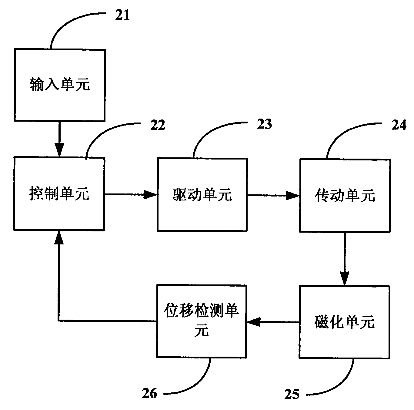
The invention was public a kind of magnet diagraph use full-automatic electromagnet and drive a control method. Drive a control method among them, include: Step A, pole head the which need to be exercised move a quantity conversion to become homologous of drive signal; Step B, drive the pole head which reigns a head in the pole to move; Step C, the feedback measures of the current of pole head move quantity; Step D, get a pole head need at present of move quantity, if moves quantity not to'0', then returning to step A, if is'0', then end. Pass system and method of the invention, not only provide high magnetic field strength to scan magnetic field and order arbitrarily of fix magnetic field, and avoided crushing to pieces phenomenon that need to be measured sample or the wound pole head occurrence. Be applicable to sparse soil specially always the easily ground magnetism material of the cobalt of magnet, plastic ...etc., satisfy market's examination to high dint of and the easily ground magnetism material need, added to repair to measure the blank in the realm, always produce, made use of to provide a data guarantee for the magnet material, show creation the economic and social performance.
Description
A fully automatic electromagnet for magnetic measurement and its drive control method technical field The invention relates to the field of magnetic property measurement of magnetic materials, in particular to a fully automatic electromagnet for magnetic measurement and a drive control method. Background technique At present, the rapid development and wide use of magnetic materials require corresponding devices to measure magnetic materials. A typical magnetic measuring system has a magnetization unit for measuring magnetic materials. As shown in FIG. 1 , the magnetization unit generally includes a magnetization winding 11 , a magnetic field detector 12 , a yoke 13 , a measuring coil 14 and pole heads 16 , and a sample 15 to be tested is placed between the pole heads. In the measurement of the sample 15 to be tested, it is first necessary to adjust the pole head 16 to the situation where it is in contact with the surface of the sample 15 to be tested through the transmis...
Claims
Login to View More Application Information
Patent Timeline
 Patent Type & Authority Patents(China)
IPC IPC(8): G01R33/12
Inventor 方岱宁饶国光
Owner 北京赛迪机电新技术开发公司

PatSnap Eureka turns technology decisions into work you can execute. Powered by our Innovation Knowledge Graph, it runs expert workflows across engineering, life sciences, materials and intellectual property. Get your review-ready output in minutes.


