
Radar

A radar and protrusion technology, applied in the field of radar, can solve the problems of difficult and high-precision grouping, difficult grouping, adverse effects, etc.

Inactive Publication Date: 2007-03-21
MURATA MFG CO LTD
View PDF1 Cites 1 Cited by
  • Summary
  • Abstract
  • Description
  • Claims
  • Application Information

AI Technical Summary

Problems solved by technology

[0008] That is to say, for objects with a relatively high relative speed to objects on the side of the road and vehicles in the reverse lane when the ego vehicle equipped with radar is traveling at high speed, the difference between the upbeat frequency and the downbeat frequency is relatively large, and it is difficult to perform an appropriate combination. group
[0009] In addition, when the traffic volume is large and there are many objects on the side of the road, many wave groups with the same orientation of the above-mentioned representative beams will be detected, so it is difficult to perform high-precision alignment
[0010] Also, due to the influence of noise waves from outside the radar and noise generated inside the radar, the prominence of the same frequency on the spectrum may also appear as an upbeat frequency and a downbeat frequency
The result is relative distances and relative velocities of objects that do not exist, or may adversely affect pairs

Method used


Image

  • Radar
  • Radar
  • Radar

Examples


Embodiment Construction

[0041] Next, the configuration of the radar according to the embodiment of the present invention will be described with reference to the drawings.

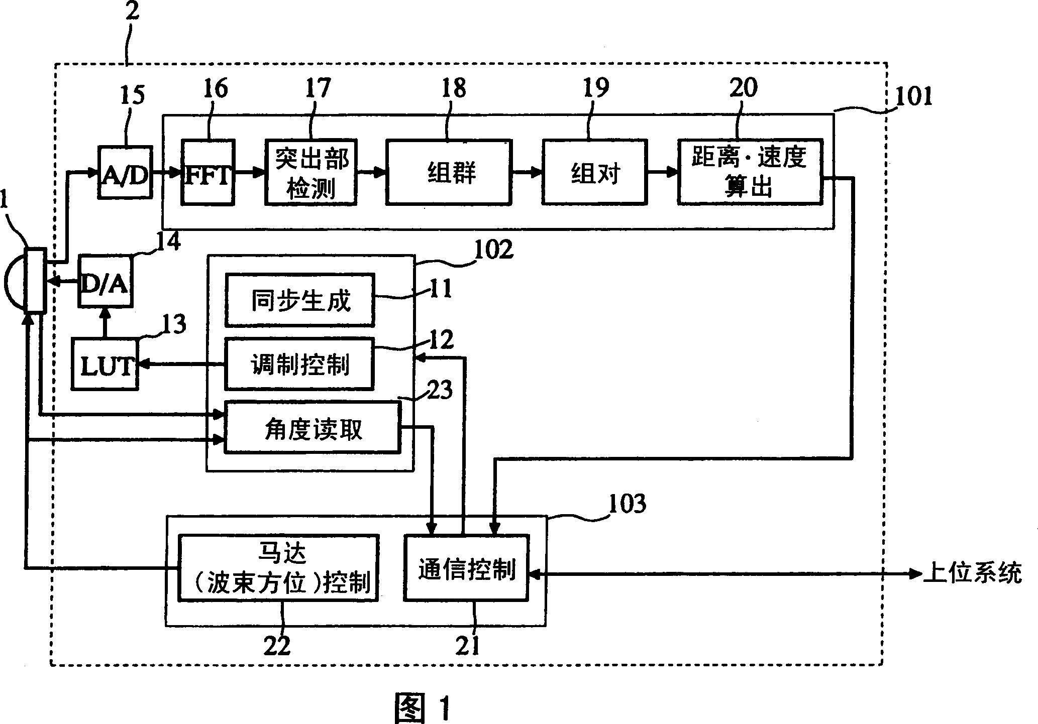
[0042] Fig. 1 is a block diagram showing the structure of a radar. In FIG. 1 , 1 is the front end for transmitting and receiving millimeter wave signals, and 2 is the radar control unit connected to the front end 1 . 101 in the radar control unit 2 denotes a signal processing unit of a beat frequency signal, 102 denotes a control unit for modulating a transmission signal and detecting a beam azimuth, and 103 denotes a part for performing beam scanning and communication control. The synchronization generator 11 generates a synchronization signal used for modulation of a transmission signal. The modulation control unit 12 outputs to the LUT 13 control data (numerical values) for transmitting a millimeter-wave signal at a transmission frequency required for each timing synchronized with the synchronization signal. This LUT 13 is a ...


PUM


Abstract

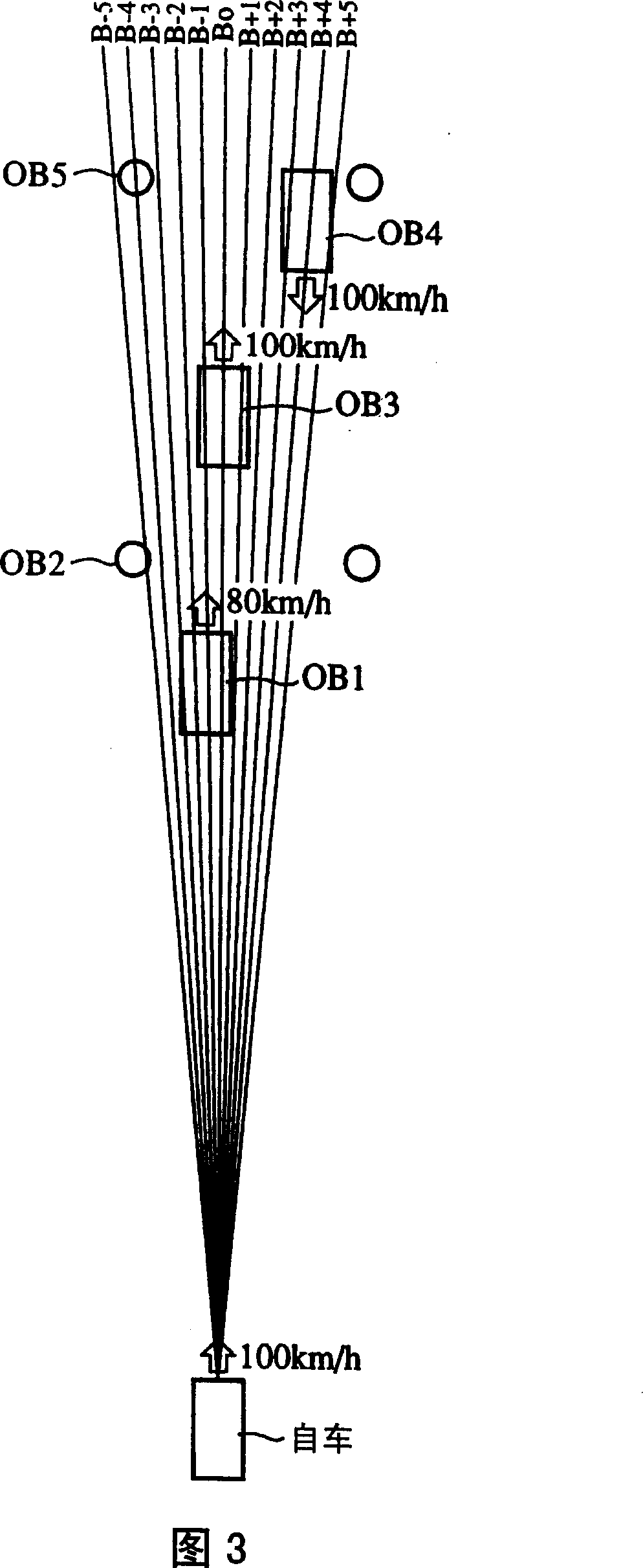
In an FM-CW radar system (2), regarding peaks appearing in the frequency spectrum of a beat signal in an FM-CW radar, groups of consecutive peaks in beam bearings within a predetermined frequency difference are regarded as being caused by reflected waves from a single target (OB1-OB5), and based on a combination of a peak group in an up-modulating interval and a peak group in a down-modulating interval, a relative distance to a target and its relative speed are determined.

Description

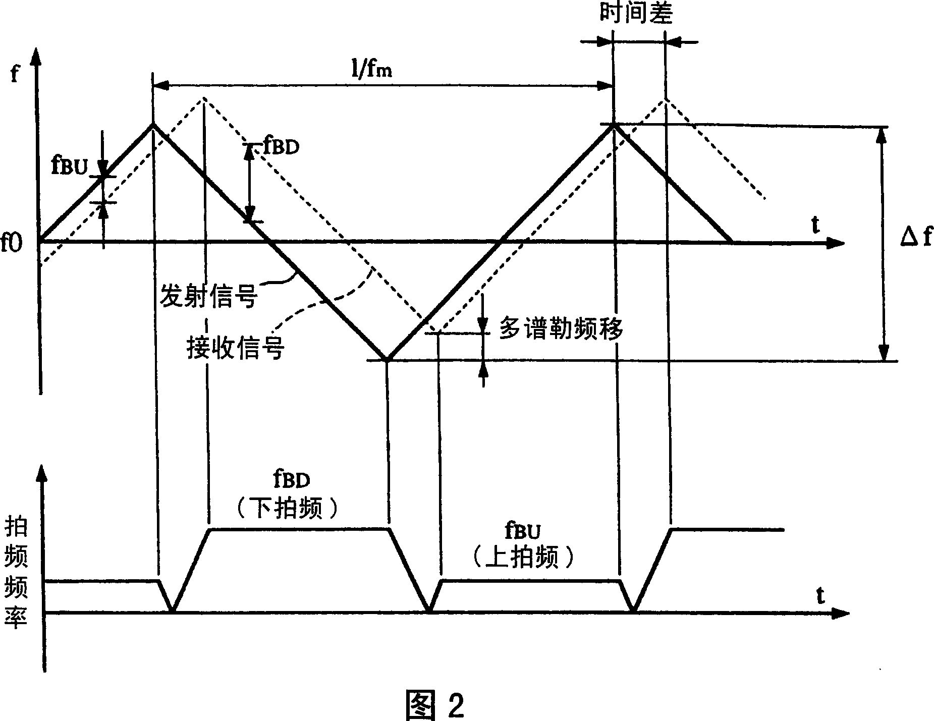
[0001] This application is a divisional application of the application whose application number is "02155956.2", the title of the invention is "radar", and the filing date is December 12, 2002. technical field [0002] The present invention relates to a radar for detecting objects by transmitting and receiving frequency-modulated electric waves of continuous waves. Background technique [0003] FM-CM radar, which detects objects by transmitting and receiving continuous wave (CW) frequency modulated (FM) radio waves, emits a time cycle formed by an ascending modulation interval in which the frequency gradually increases and a descending modulation interval in which the frequency gradually decreases The changing triangular wave transmitting signal receives the receiving signal including the reflected signal from the object object, and obtains the relative distance and relative speed of the object object according to the spectrum of the difference frequency signal of the frequen...

Claims


Application Information

Patent Timeline
IPC IPC(8): G01S7/35G01S13/34G01S13/42G01S13/58G01S13/93G08G1/16G01S13/00G01S13/931
CPCG01S13/931G01S2013/936G01S7/35G01S13/42G01S13/426G01S13/584G01S13/34G01S13/345G01S2013/9316G01S13/00
Inventor 中西基石井彻西村哲
Owner MURATA MFG CO LTD
Learn More