Breakage-proof bone-setting plate

A bone plate, anti-fracture technology, applied in the direction of outer plate, internal bone synthesis, fixator, etc., can solve the problems of reducing the strength of the bone plate, failure of bone surgery, refracture and so on

Inactive Publication Date: 2007-03-28
张庆宜
View PDF0 Cites 5 Cited by
  • Summary
  • Abstract
  • Description
  • Claims
  • Application Information

AI Technical Summary

Problems solved by technology

The setting of the screw fixing hole greatly reduces the strength of the bone plate, which will cause bending and breaking of the plate during the operation, resulting in the failure of the bone surgery; The plate will cause refracture, which greatly increases the pain of the fractured patient
[0003] In addition, the outer layer of the human bone is a smooth surface, while the traditionally used bone plate is also a smooth surface with a high degree of finish, which is difficult to locate during fracture connection surgery; Due to the free movement of the plate surface and the bone surface during comprehensive stress, the stability of the fractured bone end cannot be guaranteed, resulting in a deformed osteosynthetic deformity; the bone plate is close to the bone, and the contact area is large, which seriously affects the blood supply of the bone under the plate , easy to adversely affect fracture healing and induce local osteoporosis and refracture
[0004] There is also a bone plate with an arched base plate, although its strength is slightly higher than that of a flat plate, but the screw fixing holes also reduce the shear, bending, and torsional strength of the bone plate, which cannot overcome the problems caused by the screw fixing holes. strength defect

Method used


Image

  • Breakage-proof bone-setting plate
  • Breakage-proof bone-setting plate
  • Breakage-proof bone-setting plate

Examples


Embodiment 1

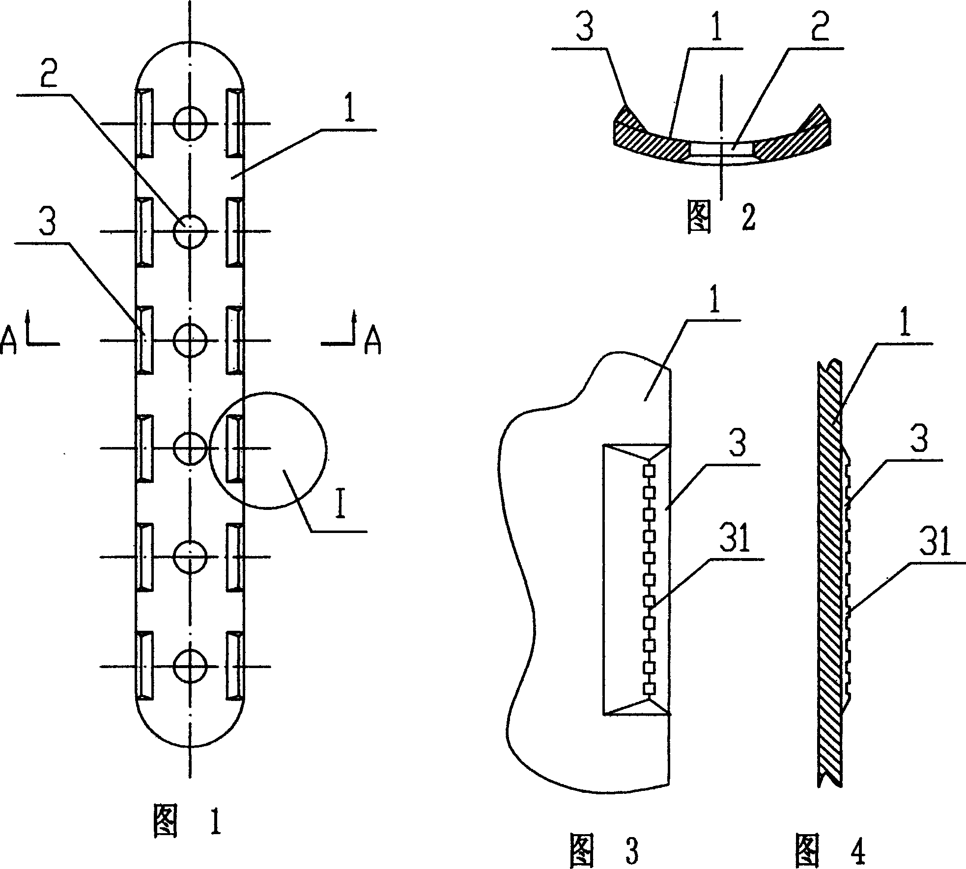
[0021] Embodiment 1: As shown in FIG. 1 , the anti-fracture bone plate includes a bone plate body 1 with an arched cross section. The bone plate body 1 is provided with screw holes 2 for bone screws to pass through. The bone plate body 1 The edge of the bone plate body near the side surface of the bone and the screw hole 2 is provided with strip-shaped protrusions 3 running along the edge of the bone plate body, and the strip-shaped protrusions correspond to the respective screw holes.

[0022] As shown in FIG. 2 , the cross-section of the strip-shaped protrusion 3 is triangular; of course, the cross-section of the strip-shaped protrusion 3 can also be rectangular, trapezoidal or semicircular.

[0023] As shown in Fig. 3 and Fig. 4, the ridges of the elongated protrusions 3 are provided with fixing teeth 31, which can enhance the adhesion between the bone plate and the bone. The contact surface between the elongated protrusion 3 and the bone plate body 1 transitions smoothly. ...

Embodiment 2

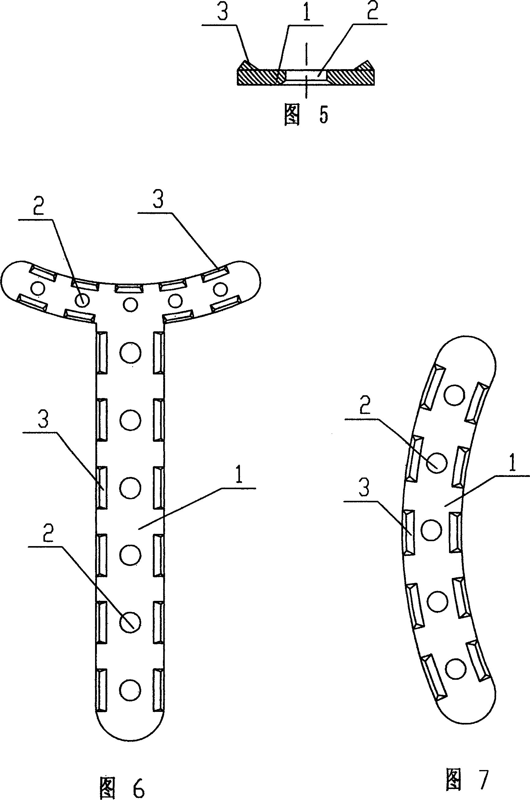
[0024] Embodiment 2: As shown in Figure 5, this embodiment is basically the same as Embodiment 1, except that the plate body 1 is in the shape of a flat plate. This structural form overcomes the disadvantage of low strength of the traditional plate-type bone plate, and is longer. The strip-shaped protrusions make the bone plate straddle the bone, bite into the cortical bone under pressure to enhance the ability of anti-sliding, anti-rotation, and anti-shearing, and the long strip-shaped protrusions create a gap between the surface of the bone plate and the outer surface of the bone , The contact area is small, which ensures the blood supply of the bone under the plate and makes the fracture easy to heal.

[0025] This embodiment is a modification of the traditional flat bone plate.

Embodiment 3

[0026] Embodiment 3: As shown in Figure 6, the shape of the osteosynthesis plate is approximately "T" shape, and other structures are the same as Embodiment 1 or Embodiment 2.


PUM


Abstract

The present invention discloses an anti-breaking bone fracture plate. It includes an arched or plate-shaped bone fracture plate self-body, on the described bone fracture plate self-body several screw holes through which the bone screws can be respectively passed are set, the side surface of the described bone fracture plate close to bone and the bone fracture plate self-body edge close to screw hole are respectively equipped with long-strip projections, said long-strip projections are correspondent to their respective screw holes, so that these long-strip projections can raise strength of screw holes, and can prevent said bone fracture plate from breaking.

Description

technical field [0001] The invention relates to a bone plate. Background technique [0002] Bone plate is currently the most commonly used internal fixation device for fracture treatment at home and abroad. And existing bone plate is a kind of simple pressurized bone plate, and it is to have several screw fixing holes on the strip plate. The setting of the screw fixing hole greatly reduces the strength of the bone plate, which will cause bending and breaking of the plate during the operation, resulting in the failure of the bone surgery; The plate will cause refracture, which greatly increases the pain of the fractured patient. [0003] In addition, the outer layer of the human bone is a smooth surface, while the traditionally used bone plate is also a smooth surface with a high degree of finish, which is difficult to locate during fracture connection surgery; Due to the free movement of the plate surface and the bone surface during comprehensive stress, the stability of ...

Claims


Application Information

Patent Timeline
IPC IPC(8): A61B17/80
Inventor 张庆宜
Owner 张庆宜
Why Eureka
Try Eureka