Disk type plastic injection moulding machine

An injection molding machine and disc type technology, which is applied in the field of disc type plastic injection molding machines, can solve the problems of low production efficiency, long stroke of the mold clamping cylinder piston, long required time, etc., and achieves simple structure, simple mechanism, The effect of reducing the time spent

Inactive Publication Date: 2007-03-28
金孝禹
View PDF1 Cites 10 Cited by
  • Summary
  • Abstract
  • Description
  • Claims
  • Application Information

AI Technical Summary

Problems solved by technology

[0005] One of the main disadvantages of this kind of injection molding machine is: since the mold clamping cylinder is set under the disc, in order to complete the mold clamping and delay pressure maintaining work, the piston of the mold clamping cylinder must move from the bottom to the top of the mold clamping hole of the disc. out and higher than the disk until the mold is pressed against the storage cy

Method used


Image

  • Disk type plastic injection moulding machine
  • Disk type plastic injection moulding machine
  • Disk type plastic injection moulding machine

Examples


Embodiment 1

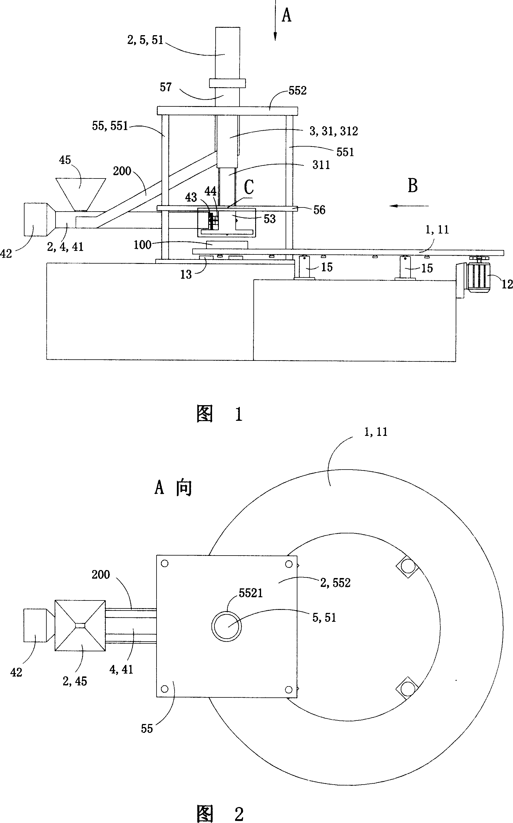
[0066] Referring to FIGS. 1 to 13 , the disc-type plastic injection molding machine of this embodiment includes a turntable device 1 , an injection device 2 for injecting plastic fluid into a mold, and a mold clamping device 3 .

[0067] 1 and 3, the turntable device 1 includes a rotatable disk 11, a drive device 12 for driving the rotation of the disk 11 and four fixed feet 15 for supporting the disk 11 (Fig. 1 and Fig. 3 have only drawn two visible fixed standoffs 15);

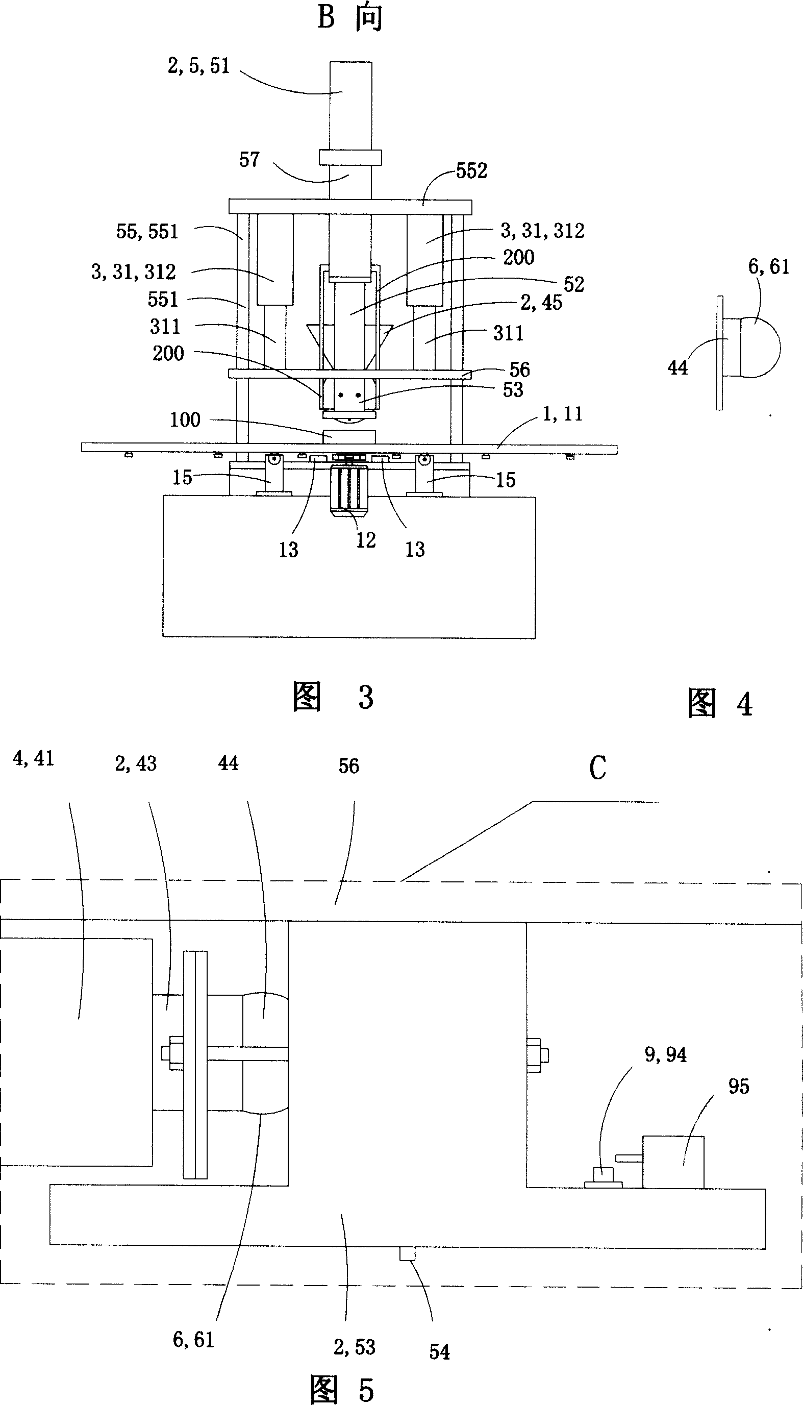
[0068] Referring to FIGS. 1 to 6 , the injection molding device 2 includes a horizontal pre-molding mechanism 4 and a vertical injection mechanism 5 .

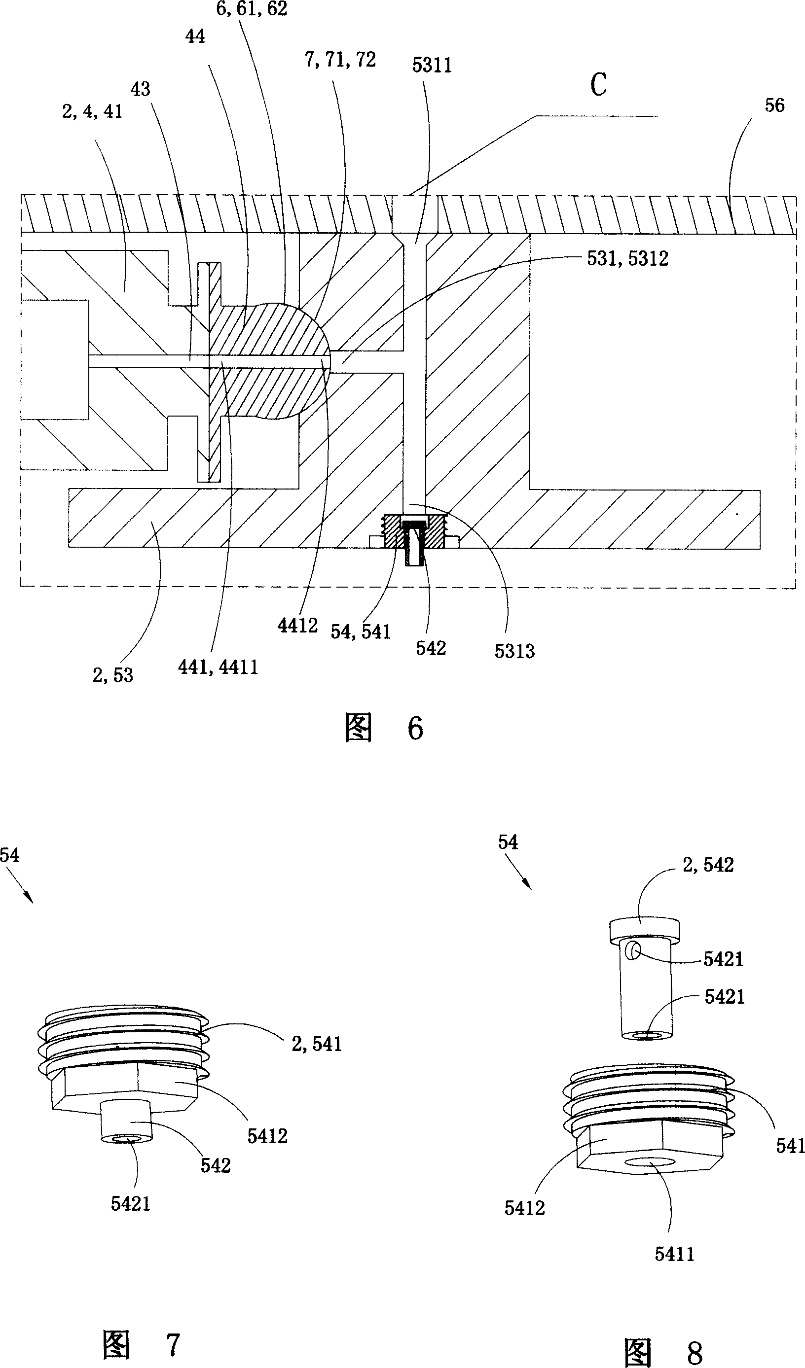
[0069] The pre-molding mechanism 4 has a plasticizing part 41, an oil motor 42, a discharge nozzle 43 and an injection coupling 44; the injection coupling 44 is provided with an injection channel 441; the inlet 4411 of the injection channel It communicates with the discharge nozzle 43 of the pre-plastic mechanism 4, and the outlet 4412 of the injection chan...

Embodiment 2

[0081] See Fig. 14 to Fig. 16, this embodiment is basically the same as Embodiment 1, the difference is that: the injection molding machine is also provided with a stop injection mechanism 9, and the stop injection mechanism 9 includes an orifice plate 91, a pick-up Plate 92, sliding pin 93, contact 94 and travel switch 95; Said orifice 91 and said clamping cylinder piston 311 are relatively fixedly arranged and can move under the driving of said clamping cylinder piston 311, and said slide The pin 93 passes through the through-hole 911 on the orifice plate 91, the lower end of the sliding pin 93 is fixedly connected to the picking plate 92, the upper end of the sliding pin 93 is fixedly connected to the contact 94, the The maximum diameter of the contact 94 is larger than the diameter of the through hole 911 on the orifice plate, and the contact 94 can trigger the travel switch 95 fixedly arranged on the orifice 91 during the upward movement. The travel switch 95 can be a mic...

Embodiment 3

[0085] See Figure 17 to Figure 20, this embodiment is basically the same as Embodiment 2, the difference is that: the injection coupling 44 is provided with a discharge connection part 6 at the outlet 4412 of the injection channel, and the discharge connection part 6 is shaped as a truncated conical tenon 62 with a protruding conical surface 61, and an injection channel outlet 4412 is provided at the center of the discharge connection part 6; A feed connection part 7 is provided, the shape of the feed connection part 7 is a conical groove 72 with a concave tapered surface 71, and the injection head feed port 5312 is located at the center of the feed connection part 71 place; the shape of the discharge connection portion 6 of the injection coupler 4 matches the shape of the feed connection portion 7 of the injection head 53 .


PUM


Abstract

The present invention relates to a circular disk type plastics injection moulding machine. It includes rotary disk device, injection moulding device and mould-closing device. The described rotary disk device includes rotatable circular disk and drive device for driving circular disk and making it be rotated; The described injection moulding device includes horizontal pre-injection mechanism and vertical injection mechanism; and the mould-closing device includes a mould-closing hydraulic cylinder over the circular disk. Said invention also provides its working principle and operation method.

Description

technical field [0001] The invention belongs to a plastic injection molding machine, in particular to a disc type plastic injection molding machine. Background technique [0002] Disc-type plastic injection molding machine is a kind of equipment specially used for manufacturing plastic soles. The discs used are often equipped with multiple sole molds of the same style and different sizes at the same time. Therefore, it is necessary to set the molds on the turntable for plastic injection. The molding machine injects and molds the molds with the same style and different code numbers in stages, and facilitates the mold opening and taking out the molded soles. [0003] Chinese patent 00229774.4 discloses a disc type injection molding machine for producing plastic shoe soles, including screw pre-molding mechanism, injection mechanism, mold clamping mechanism, hydraulic energy storage system and turntable part; The material end is connected with a switching seat equipped with a s...

Claims


Application Information

Patent Timeline
IPC IPC(8): B29C45/64B29C45/07B29C45/06B29C45/46B29C45/72B29C45/17B29C45/20B29C45/23
Inventor 金孝禹
Owner 金孝禹
Why Eureka
Try Eureka