Damage-free detection system for strong conveying belt

A non-destructive testing, conveyor belt technology, applied in the use of radiation for material analysis, etc., can solve the problems of adverse reactions, long detection time, low efficiency, etc., to achieve image contrast and definition enhancement, spatial resolution improvement, system resolution high effect

Inactive Publication Date: 2007-03-28
天津城信通科技发展有限公司
View PDF0 Cites 18 Cited by
  • Summary
  • Abstract
  • Description
  • Claims
  • Application Information

AI Technical Summary

Problems solved by technology

[0004] The traditional inspection of conveyor belt joints by using X-ray machine is to observe under the condition that the conveyor belt is still. Although this kind of observation instrument is intuitive, production must be stopped during detection, and real-time online monitoring of steel cord conveyor belts cannot be realized.
In addition, manual operation has high labor intensity, low efficiency, long detection time, exposure to X-rays, detection personnel will have some adverse reactions, long-term use will seriously affect the health of operators
Secondly, because the X-ray machine cannot work continuously for a long time, the detection of the entire length of the conveyor belt cannot be carried out, so that the newly broken rope and rust of the conveyor belt cannot be found in time, leaving hidden dangers to the operation of the conveyor belt.

Method used


Image

  • Damage-free detection system for strong conveying belt
  • Damage-free detection system for strong conveying belt
  • Damage-free detection system for strong conveying belt

Examples


Embodiment Construction

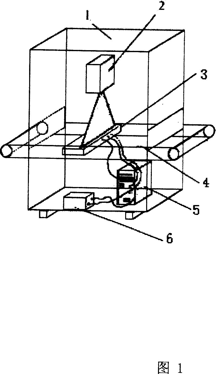
[0039] The non-destructive detection system of the strong conveyor belt of the present invention will be further described below in conjunction with the accompanying drawings.

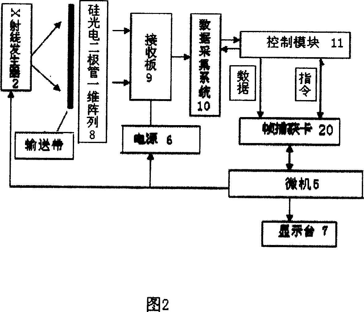
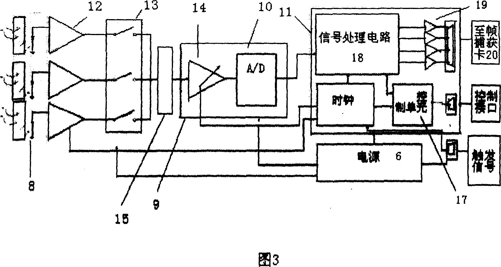
[0040] The structure of the strong conveyor belt non-destructive testing system of the present invention is that there is a T-140 type X-ray generator 2 that can work continuously in the monitoring system box and radiation shielding 1, and is placed on one side of the strong conveyor belt of the object under test, and the X-rays generate The X-rays sent by the device 2 pass through the strong conveyor belt and are received by the X-ray receiving / control board 3 placed on the opposite side of the strong conveyor belt. The X-ray receiving / controlling board 3 includes a one-dimensional array 8 composed of photoelectric cells, and the electrical signals containing image pixels of the object under test are amplified and filtered before being sequentially collected. After the analog signal is amplified by th...


PUM


Abstract

This invention provides a harmless detection system for powerful transportation belts, in which, an X ray generator working continuously is set at the side of a being tested object-the powerful transportation belt in the system box and radiation shield, said generator emits X rays passing through the belt to be set at the related position of the opposite side of the transportation belt, which is received by the receiving/control board, which includes that an one-way array composed of photoelectric tubes emits electric signals containing image pixels of the being tested object to be collected orderly after amplification and filtration, after the analog signals are amplified, they pass through a D/A converter and parallel/serial converter to generate parallel image pixel digital signals to be transmitted to a frame capture card in the microcomputer, therefore, said serial data flow is analyzed into a digital signal and a control signal to pass through an image analysis system to generate a detailed analysis report forms to be observed directly on the display or printed.

Description

technical field [0001] The present invention relates to an image technology (image acquisition technology, image processing analysis technology and image automatic recognition technology), optical technology, artificial intelligence technology, precision machinery manufacturing technology, electronic technology, sensor technology, non-destructive testing technology and modern computer technology design A non-destructive testing system for a strong conveyor belt with an explosion-proof function. Background technique [0002] Today's coal mines, especially large coal mines, have an annual production capacity of several million tons, or even more. And mine hoisting generally adopts inclined shaft hoisting with strong conveyor belt machine. Therefore, whether the strong conveyor belt can be transported safely and efficiently directly affects the production efficiency and safety production status of the coal mine. During the operation, whether the wire rope of the conveyor belt...

Claims


Application Information

Patent Timeline
Patent Type & Authority Applications(China)
IPC IPC(8): G01N23/04G01N23/18
Inventor 崔才英李文焦克华
Owner 天津城信通科技发展有限公司
Why Eureka
Try Eureka