High-power relay

A technology of high-power relays and relay coils, applied in the direction of relays, electromagnetic relays, detailed information of electromagnetic relays, etc., can solve problems affecting the normal operation of electrical systems, achieve the effects of small voltage drop, improved product reliability, and large passing current

Inactive Publication Date: 2007-03-28
FAW GROUP
View PDF0 Cites 0 Cited by
  • Summary
  • Abstract
  • Description
  • Claims
  • Application Information

AI Technical Summary

Problems solved by technology

[0002] The back electromotive force generated by the coil of the current relay at the moment of switching on and off can generate electromagnetic interference to the electrical system of the vehicle, especially to various controllers (ECUs) on the vehicle, affecting the normal operation of the electrical system

Method used


Image

  • High-power relay

Examples


Embodiment Construction

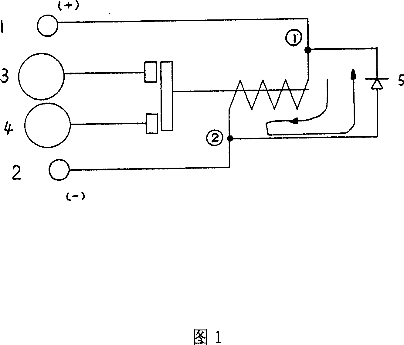
[0007] Below in conjunction with accompanying drawing, the present invention is further described: as shown in Figure 1, high-power relay is characterized in that: a freewheeling diode 5 is connected in parallel at relay coil 1 and 2 two ends, and coil and freewheeling diode 5 form a circuit Induction potential absorption; induction current circulates in the 2→5→1 loop until the energy consumption is exhausted. Contacts 3 and 4 are made of silver metal oxide material. When the relay is working normally, the current is from 1→2. At this time, the freewheeling diode 5 is in the reverse cut-off state. When the coil is powered off, the characteristics of the coil itself will maintain the original state within a short period of time. The current direction remains unchanged. At this time, if there is no freewheeling diode 5, the induced potential generated will interfere with other electrical equipment through 2 (ground wire). If a freewheeling diode 5 is added, the coil and the fre...


PUM


Abstract

Characters of the relay in large power are that a freewheeling diode, a winding and a diode are connected to two ends of winding of relay to constitute a loop to absorb induced electromotive force; material of silver metallic oxide is adopted for contacts. The disclosed relay allows large current to pass through under small voltage drop. Comparing with same kind of product, the disclosed product raises reliability greatly.

Description

Technical field: [0001] The invention relates to a high-power relay, which belongs to the starting / preheating functional parts in the field of auto parts. Background technique: [0002] The counter electromotive force generated by the coil of the current relay at the moment of switching on and off can generate electromagnetic interference to the electrical system of the whole vehicle, especially to various controllers (ECUs) on the vehicle, and affect the normal operation of the electrical system. Invention content: [0003] The purpose of the present invention is to provide a high-power relay. By connecting freewheeling diodes in parallel at both ends of the relay coil, the back electromotive force generated by the coil of the relay at the moment of switching on and off is eliminated from affecting the electrical system of the whole vehicle, especially on all parts of the vehicle. Electromagnetic interference of a controller (ECU). The silver metal oxide material is used...

Claims


Application Information

Patent Timeline
Patent Type & Authority Applications(China)
IPC IPC(8): H01H47/00H01H47/02H01H50/54H01H1/02
Inventor 李国辉于萌吴国良
Owner FAW GROUP
Why Eureka
Try Eureka