Electromechanical integrated machine tool chuck directly constituted of external rotor rotating electric machine

A technology of rotating electrical machines and external rotors, applied to synchronous motors with stationary armatures and rotating magnets, chucks, electromechanical devices, etc., can solve problems such as raw materials, energy, capital, and time consumption, and achieve international competitiveness , Simple structure, saving power consumption

Inactive Publication Date: 2007-03-28
任海
View PDF0 Cites 2 Cited by
  • Summary
  • Abstract
  • Description
  • Claims
  • Application Information

AI Technical Summary

Problems solved by technology

All this has resulted in huge consumption of raw materials, energy, capital, time, etc. in the entire machinery and equipment manufacturing industry.

Method used


Image

  • Electromechanical integrated machine tool chuck directly constituted of external rotor rotating electric machine

Examples


Embodiment Construction

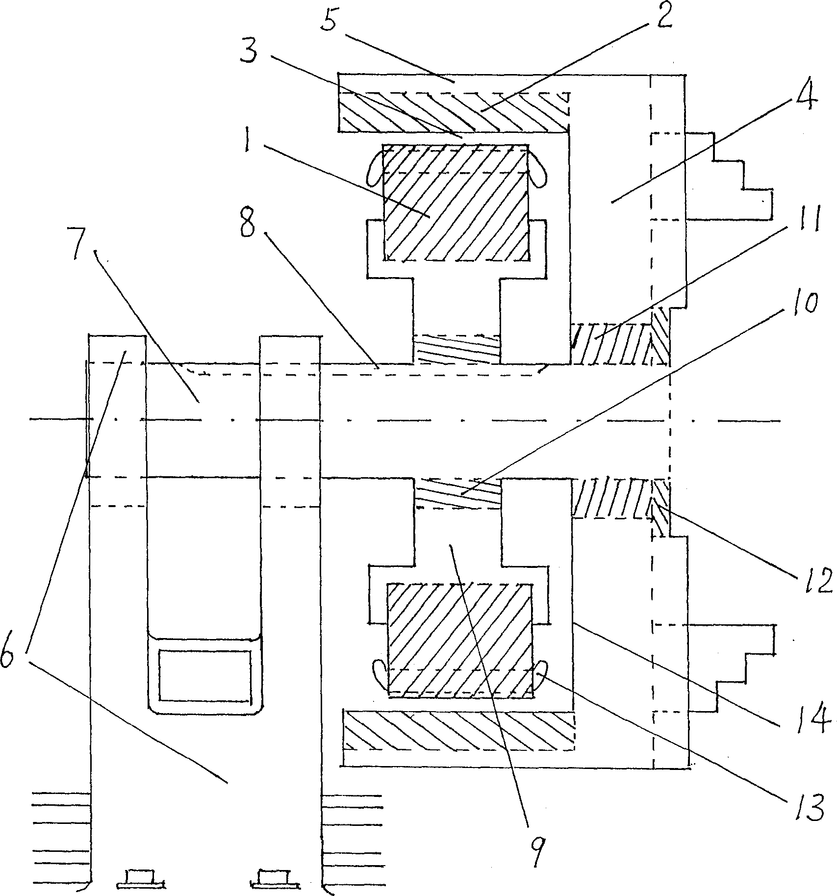
[0009] The specific implementation manners of the invention of the present application will be described in further detail below in conjunction with the accompanying drawings.

[0010]What is shown in the accompanying drawings is an embodiment of the invention of the present application. People can use traditional mechanical connection installation methods such as pins, keys, screws, etc., to firmly inlay and install the secondary rotor ring body 2 of the outer rotor rotary motor on the extension part 5 of the outer circular shell edge of the chuck 4 of the horizontal machine tool. in. The machine tool chuck 4 is installed and fixed on the main shaft 7 through the bearing 11 or the bearing bush 11, and can rotate in any direction. The inner end surface of the bearing 11 or the bearing bush 11 is protected by a spindle step, or a circular gasket, or an inner end cover; the outer end surface is protected by an outer end cover 12 . The main shaft 7 is horizontally installed and...


PUM


Abstract

Primary stator of external rotor of electric rotating motor is installed on fixed not revolving principal axis. Being coupled to clamping chuck of machine tool to constitute a mechanical whole, the secondary rotor of the motor is rotated around principal axis. New type machine tool of using the said clamping chuck of machine tool discards headstock completely. Using converter technique, voltage-regulating technique makes the clamping chuck of machine tool obtain each moment and rotate speed. Advantages are: simple structure, compact, lightness, low cost, easy installation and maintenance.

Description

technical field [0001] The invention of the present application relates to a mechatronic machine tool chuck directly constructed from the primary stator and secondary rotor of an outer rotor rotating electrical machine. Background technique [0002] In the prior art, no matter it is a horizontal machine tool, a vertical machine tool, an automatic lathe, a numerical control machine tool, a frequency conversion machine tool, etc., there is a valuable and huge machine tool spindle box, which is equipped with a large number of mechanical speed change gears, transmission Shafts, clutches, etc.; even if the frequency conversion machine tool does not use a complete headstock, there is at least one transmission belt and two pulleys that transmit the rotational torque to the machine chuck. These mechanical transmission devices in the machine tool structure are to transmit the motor power to the machine tool chuck and its workpiece. The machine tool spindle box is not only the main p...

Claims


Application Information

Patent Timeline
IPC IPC(8): H02K21/22H02K17/00H02K7/14H02K5/10H02K5/22H02P27/02H02P27/04B23B31/02B23B19/00B23B19/02
CPCB23B31/02H02K7/085B23B2260/062H02K1/187B23Q5/10
Inventor 任海
Owner 任海
Why Eureka
Try Eureka