

Friction transmission belt
A transmission belt, friction coefficient technology, applied in transmission belts, V-belts, belts/chains/gears, etc., can solve problems such as noise, poor wettability, and reduced transmission performance
- Summary
- Abstract
- Description
- Claims
- Application Information
AI Technical Summary
Problems solved by technology
Method used
Image

Examples
Embodiment 1 and 2
[0114] Embodiment 1 and 2, comparative example 1
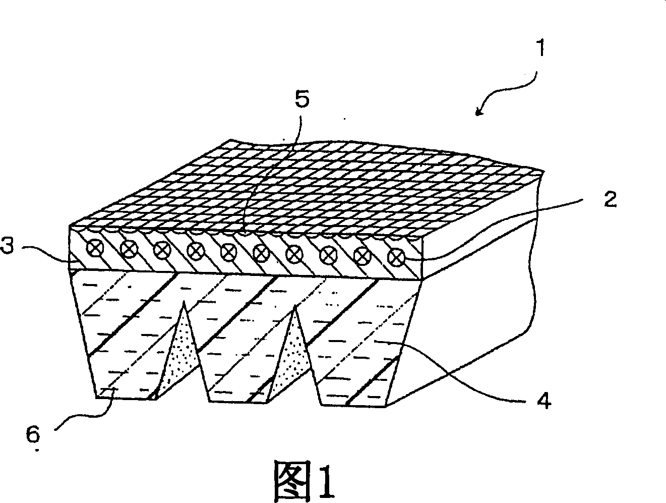
[0115] Each of the V-ribbed belts in Examples 1-2 and Comparative Example 1 was formed as follows: a tension member formed of a rope made of polyester fiber was embedded on one side of the adhesive rubber layer, and cotton with rubber A double layer of canvas is stacked on the above-mentioned side of the adhesive rubber layer, and then three rib portions are arranged in the longitudinal direction of the belt on the compressed rubber layer, which is placed on the other side of the adhesive rubber layer.
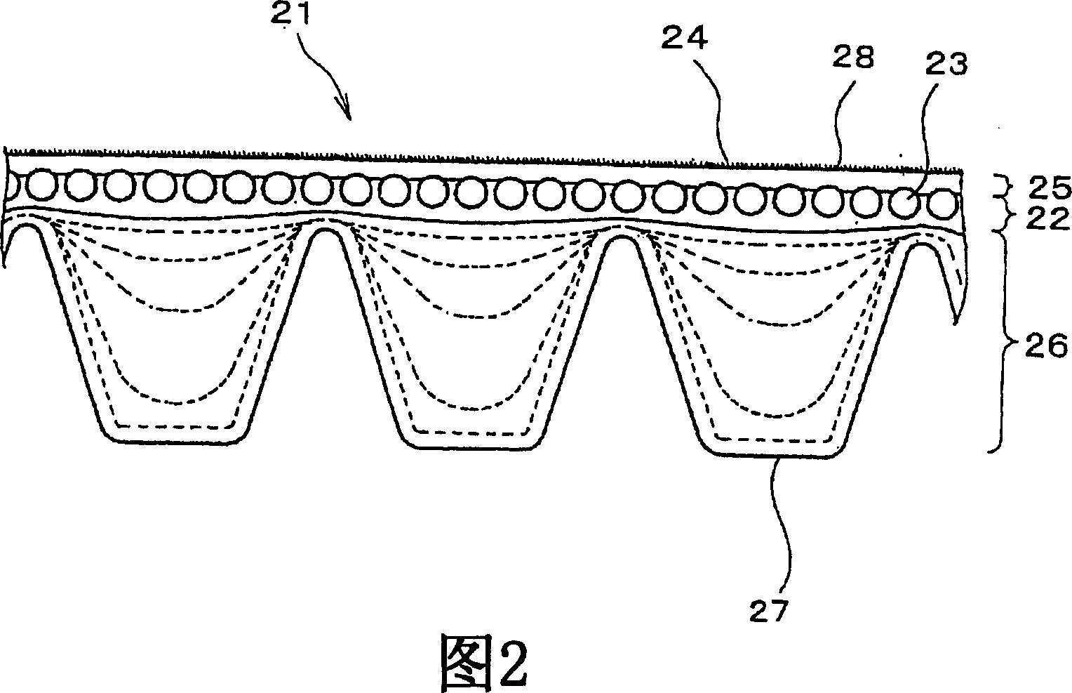
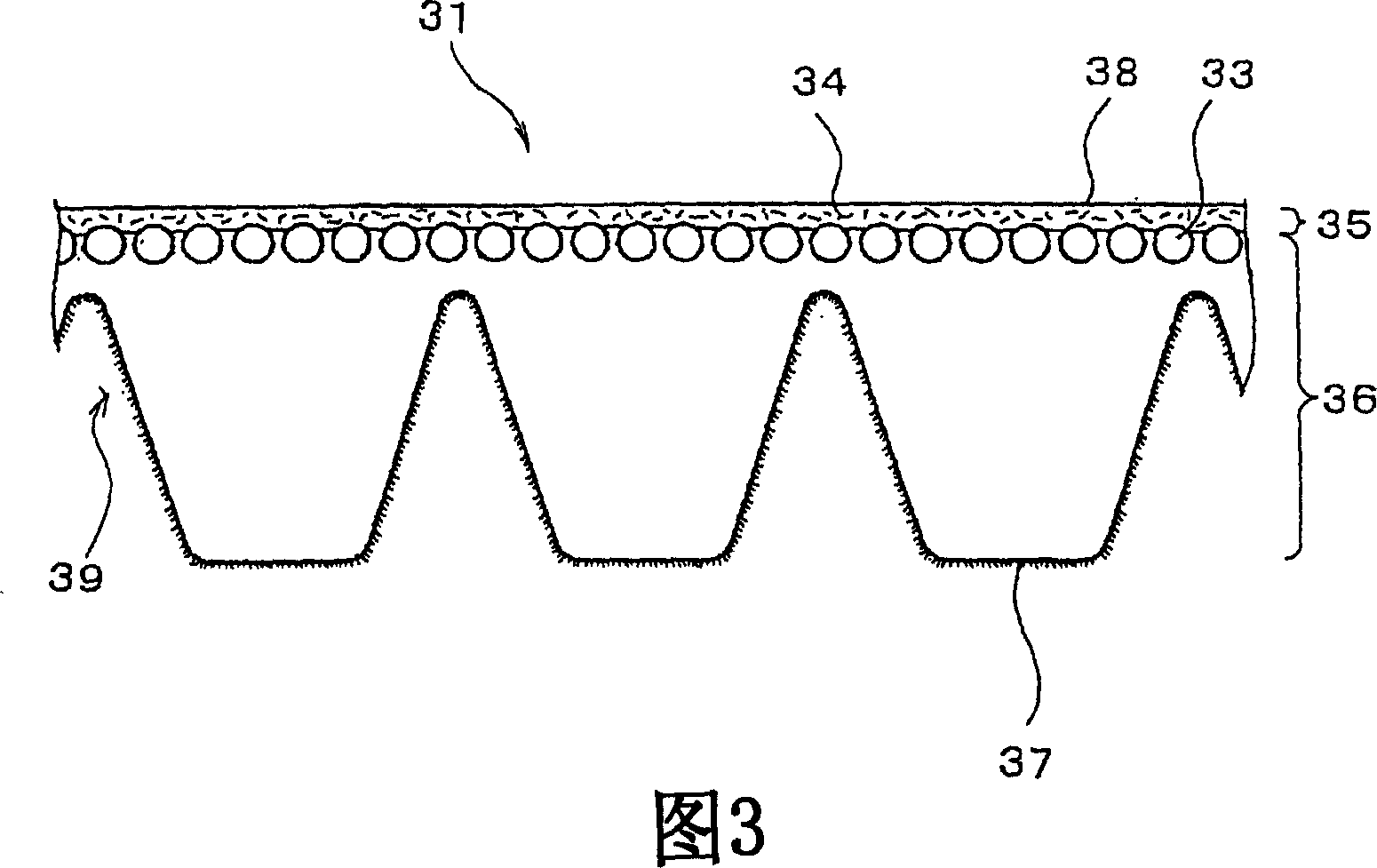
[0116] Each compression layer was obtained by adjusting the rubber composition shown in Table 1, kneading with a Banbury mixer, and rolling with a calender roll. The compressive layer contains short fibers, and the short fibers are oriented in the width direction of the belt. The rubber content of each adhesive layer, in which short fibers were excluded from the rubber composition, is shown in Table 1. The physical propertie...
Embodiment 2
[0140] Example 2 shows similar properties to Example 1 as shown in FIGS. 7 , 8 and 9 .
PUM
| Property | Measurement | Unit |
|---|---|---|
| specific surface area | aaaaa | aaaaa |
| particle diameter | aaaaa | aaaaa |
| roughness | aaaaa | aaaaa |
Abstract
Description
Claims
Application Information