
Light polarizer for display device and its production

A display and polarizing technology, which is applied in optics, instruments, polarizing components, etc., can solve the problems of insignificant improvement of two-side viewing angle, limited improvement of contrast and color saturation, etc.

Inactive Publication Date: 2007-04-04
OPTIMAX TECHNOLOGY CORPORATION
View PDF0 Cites 2 Cited by
  • Summary
  • Abstract
  • Description
  • Claims
  • Application Information

AI Technical Summary

Problems solved by technology

[0006] Therefore, in addition to the insignificant improvement in the two-side viewing angle, this method cannot improve the dark color shift effect of the liquid crystal display. In addition, the contrast ratio of the two-side viewing angle and very limited improvements in color saturation

Method used


Image

  • Light polarizer for display device and its production
  • Light polarizer for display device and its production
  • Light polarizer for display device and its production

Examples


Embodiment Construction

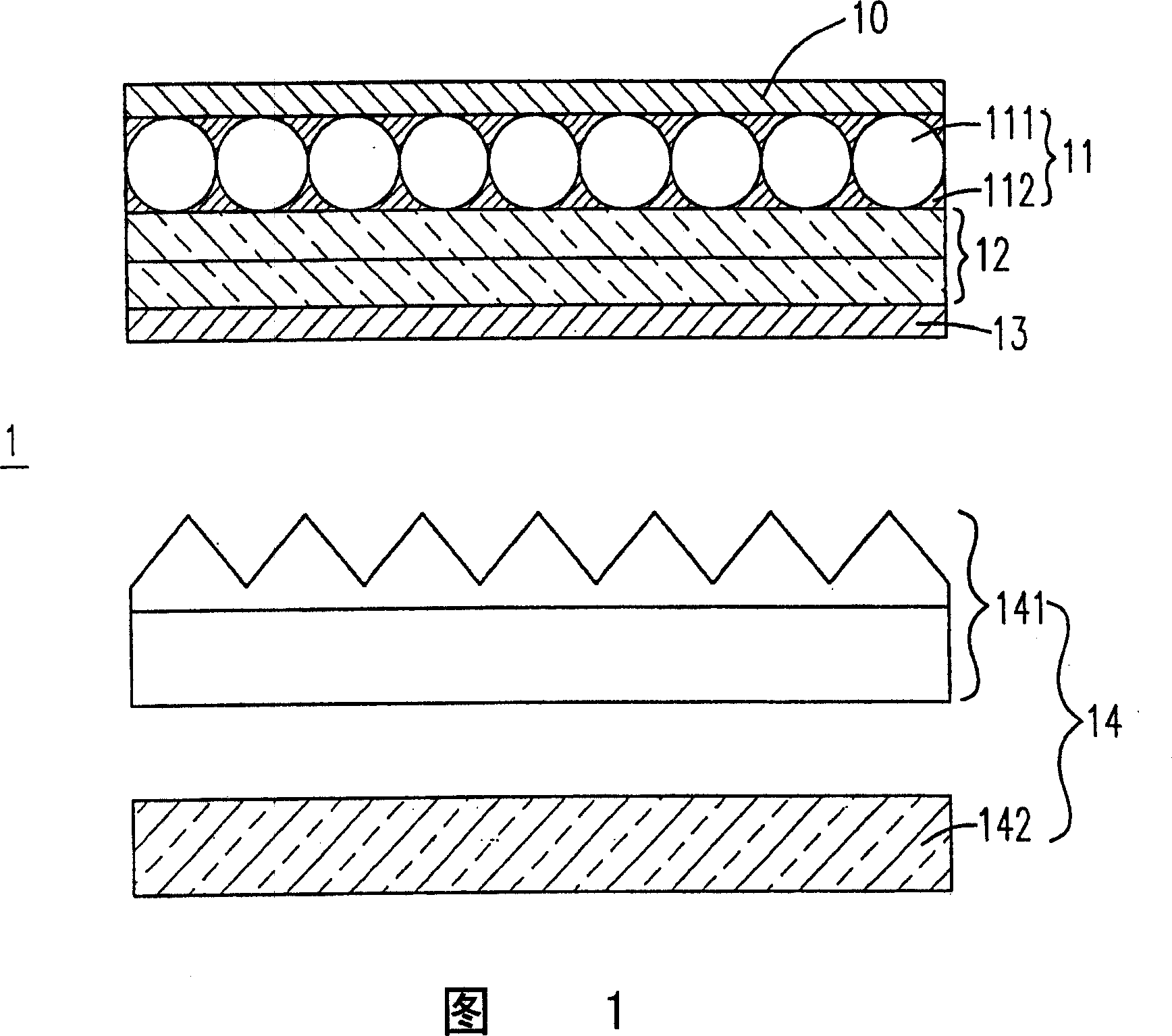
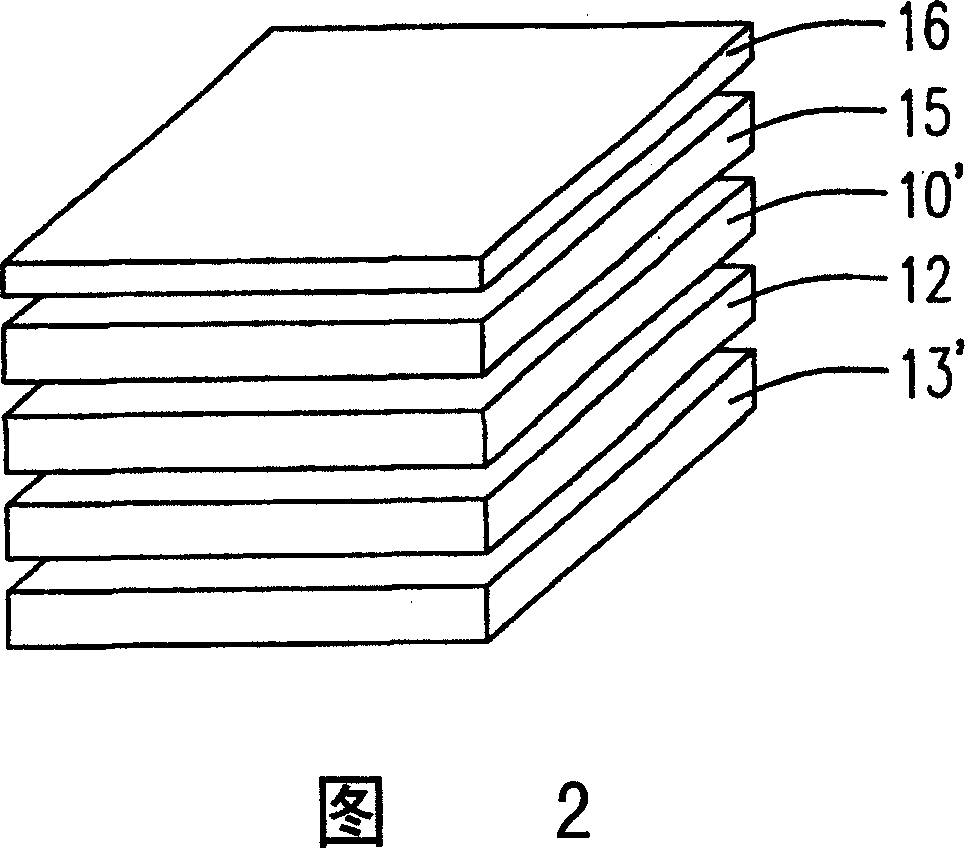
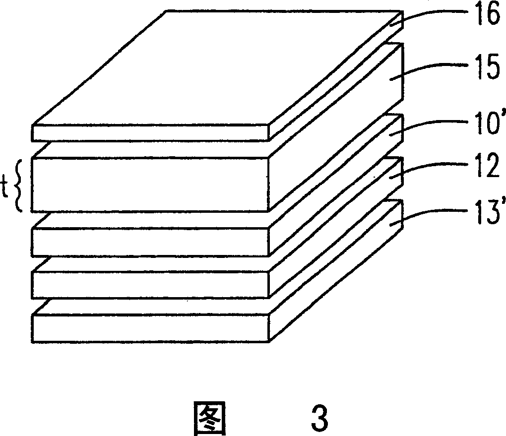
[0019] Please refer to FIG. 2 , which is a schematic diagram of an embodiment of a display with a viewing angle compensation device of the present invention. Wherein a liquid crystal panel 12 is arranged between the upper polarizer 10' and the lower polarizer 13'. In order to solve the problem that the traveling direction of the light caused by the light passing through the polarizing device is too fixed, resulting in too narrow viewing angle, the present invention also sets a viewing angle compensating device on the upper polarizing plate 10', which has a first diffusion layer 15, the first The diffusion layer 15 includes a plurality of particles and fillers, and the original traveling direction is changed from a single direction to multiple directions by light hitting the particles, so as to achieve the effect of viewing angle compensation. The diameter distribution of the particles ranges from several nanometers to tens of microns, and is uniformly distributed.

[0020] Th...


PUM


Abstract

A method for prepared polarization unit applied on display forms at least one diffusion layer on display face plate or on polarization plate of said display for raising visual angle scope of said display.

Description

technical field [0001] The invention relates to a polarizing device applied to a display and a manufacturing method thereof, in particular to a polarizing device with a viewing angle compensation device. Background technique [0002] With the rapid development of Internet and wireless communication technology, informatization is gradually popularized among individuals. Therefore, portable information products, such as notebook computers, mobile phones, digital cameras, and personal digital assistants, etc., are developing and growing rapidly. [0003] Due to the advantages of thinness, light weight, low power consumption, no radiation pollution, and compatibility with semiconductor process technology, etc., and in line with the rise of the Internet digital information market, liquid crystal displays have made it possible in just 30 years , the application of products has grown by leaps and bounds; from the early application of simple watches, computers and other low informat...

Claims


Application Information

Patent Timeline
IPC IPC(8): G02F1/1335G02B5/30
Inventor 刘育维梁逸平徐荣鸿吴龙海
Owner OPTIMAX TECHNOLOGY CORPORATION
Learn More