Grey mask and method for making it

A technology of gray-tone mask and manufacturing method, which is applied in the direction of semiconductor/solid-state device manufacturing, photolithographic process exposure device, patterned surface photographic process, etc., which can solve the problem of difficult precise control of film thickness, large aspect ratio, and practical Difficulty and other issues

Inactive Publication Date: 2011-12-07
HOYA CORP
View PDF1 Cites 0 Cited by
  • Summary
  • Abstract
  • Description
  • Claims
  • Application Information

AI Technical Summary

Problems solved by technology

However, in this method, since the film thickness is too thick, the aspect ratio (the ratio of the pattern size to the height) is large. As a result, the pattern shape and pattern accuracy of the light-shielding part are poor, and the etching time is long.
In addition, in fact, it is difficult to accurately control the film thickness by half etching, and it is difficult to use it practically.

Method used


Image

  • Grey mask and method for making it
  • Grey mask and method for making it
  • Grey mask and method for making it

Examples


Embodiment Construction

[0083] Next, a first embodiment of the present invention will be described.

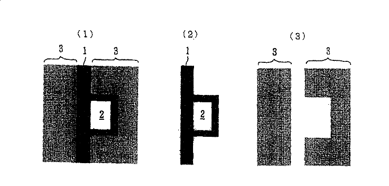
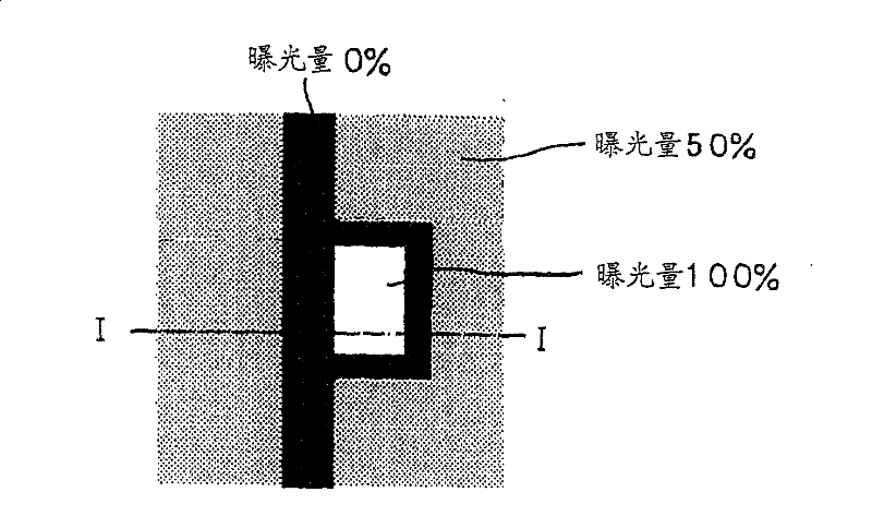
[0084] Synthetic data when all graphic data including the shading part, light-transmitting part and gray tone part are included, such as figure 1 As shown in (1), the case where the light-shielding part 1 and the light-transmitting part 2 (such as an amorphous silicon pattern of TFT) and the gray tone part 3 (semi-transmitting part and semi-transmitting part) formed around them is taken as an example. In this situation, figure 1 The data of the light shielding part 1 and the light transmitting part 2 shown in (2) and figure 1 Data separation of the gray tone section 3 shown in (3). Then, after drawing the light-transmitting portion with the exposure amount (100%) that can completely remove the resist, the gray tone portion 3 (semi-transmission portion or semi-transmission portion Translucent part), can be figure 1 (1) A depiction of the graph shown. in the case of figure 1 The drawing patt...


PUM

PropertyMeasurementUnit
thicknessaaaaaaaaaa
thicknessaaaaaaaaaa
transmittivityaaaaaaaaaa

Abstract

In a control circuit for a power converting apparatus, such as a three-phase inverter, unnecessary switching operations of switching elements are avoided. The control circuit includes current sensors for detecting inverter currents; a three-phase current command generating circuit for generating a current command value; adders / substracters for calculating current deviation between the current command value and the inverter current; a voltage detecting circuit for detecting voltages of three-phase power supplies; and a pulse width modulation (PWM) pattern selector circuit obtaining a current deviation vector from the current deviation, setting an allowable range region with respect to the current deviation vector, when the current deviation vector is not located within the allowable range region, obtaining a moving direction of the current deviation vector as to output voltage vectors of the power converting apparatus based upon the power supply voltage vector, and outputting an output voltage vector in which the moving direction of the current deviation vector, among moving directions, is directed to the allowable range region.

Description

[0001] This application is a divisional application of a Chinese invention patent application with an application date of June 18, 2002, an application number of 02123331.4, and an invention title of "gray tone mask and its manufacturing method". technical field [0002] The present invention relates to a gray tone mask, its manufacturing method and the like. Background technique [0003] In recent years, in the field of masks for large LCDs, attempts have been made to reduce the number of masks using grayscale masks (Monthly FPD Intelligence, May 1999). [0004] Here, a grayscale mask, for example, such as Figure 5 As shown in (1), it has a light-shielding part 1 , a light-transmitting part 2 and a gray tone part 3 . The gray-tone part 3 is an area where a fine light-shielding pattern 3a is formed within the resolution limit of a large-scale LCD exposure machine using a gray-tone mask. The purpose of its formation is to reduce the amount of light transmitted through this a...

Claims


Application Information

Patent Timeline
Patent Type & Authority Patents(China)
IPC IPC(8): G03F1/14G03F7/09G03F7/20G03F7/26H02M7/48
CPCH02M2007/53876H02M7/53873H02M2001/0012H02M1/0012H02M7/53876
Inventor 野津手重德
Owner HOYA CORP
Why Eureka
Try Eureka