Super wide band antenna

A technology of ultra-wideband antenna and microstrip line, which is applied in the field of communication, can solve the problems of increasing the volume and weight of the antenna, interfering with the working performance of the ultra-wideband system, and being uneconomical and practical, and achieve the effect of filtering out interference signals

Inactive Publication Date: 2007-04-11
ZHEJIANG UNIV
View PDF0 Cites 12 Cited by
  • Summary
  • Abstract
  • Description
  • Claims
  • Application Information

AI Technical Summary

Problems solved by technology

Working in such a wide frequency band will cause a problem: that is, the antenna may receive signals from one or several other narrowband systems operating in this frequency range in the same environment, such as wireless local area network (Wireless Local Area Network, WLAN ) Its working frequency is between 5GHz-6GHz, which is also included in the working frequency range of the

Method used


Image

  • Super wide band antenna
  • Super wide band antenna
  • Super wide band antenna

Examples


Embodiment Construction

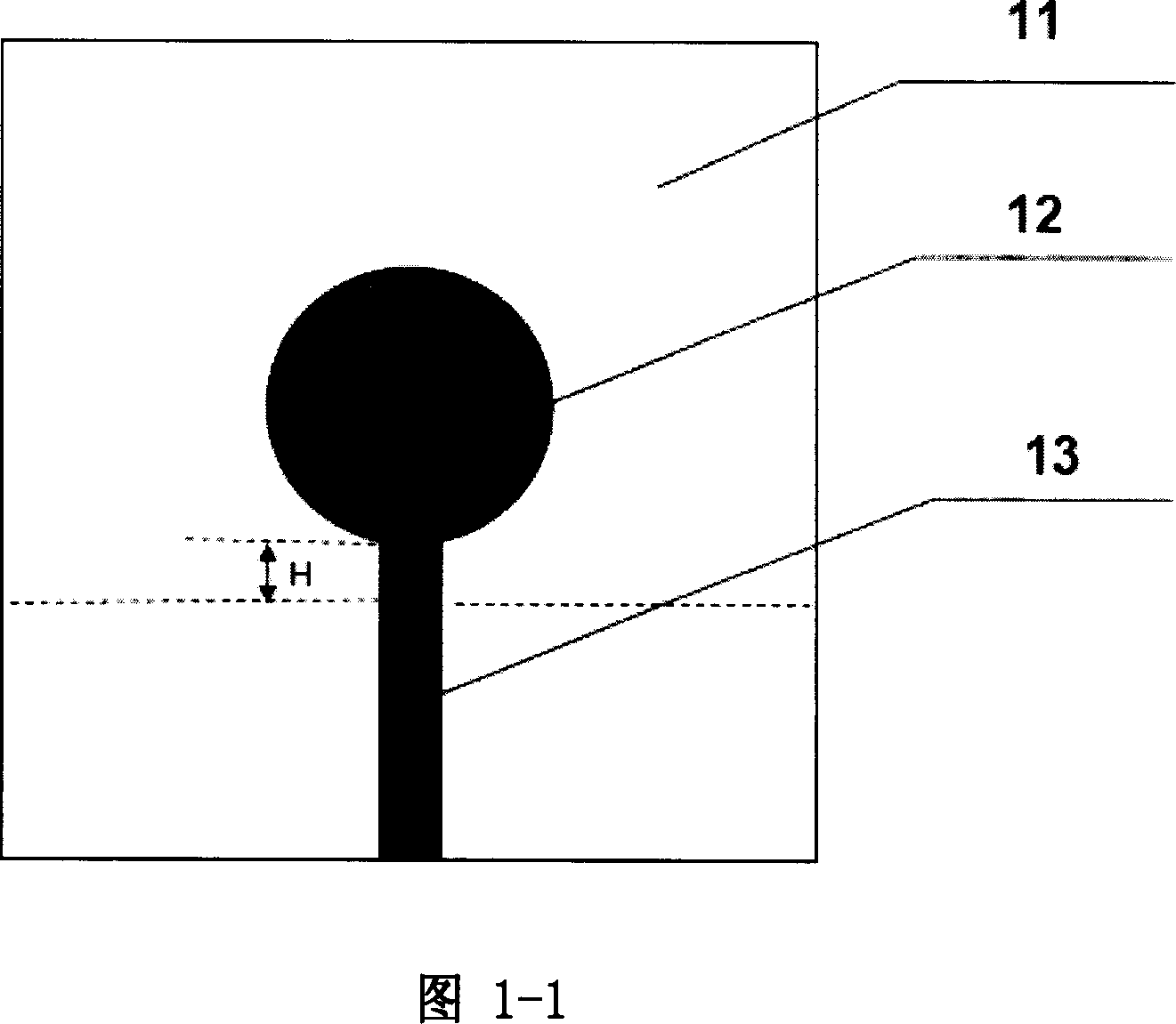
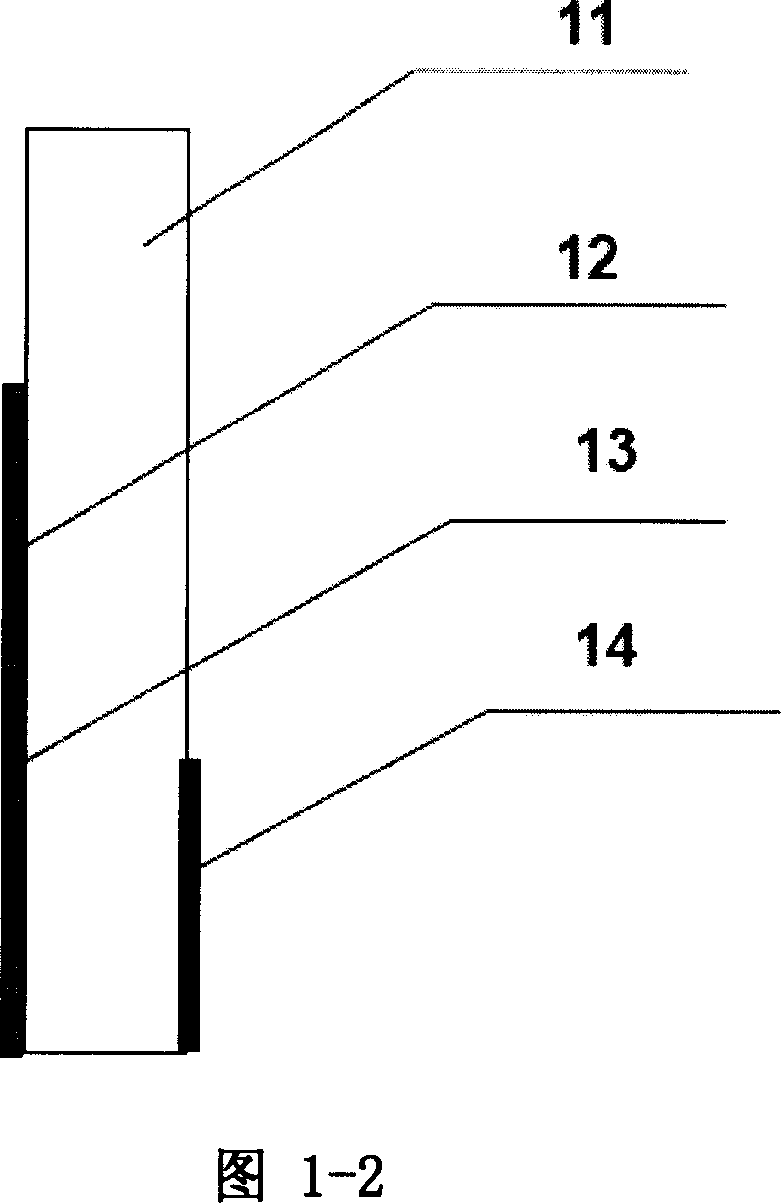
[0018] Referring to FIG. 1 , it shows a schematic structural diagram of an existing ultra-wideband antenna unit. The antenna is a monopole antenna, including a circular metal piece 12 (radius is about 10 mm) attached to the top surface of the dielectric base plate 11 . The material of the dielectric bottom plate 11 is a material with a relatively high dielectric coefficient, such as a material with a relative dielectric coefficient of 10.2. The bottom surface of the dielectric chassis is partially covered with metal 14 as a ground. The edge of the circular metal sheet 12 is connected with a section of microstrip line 13 as a feeder. Connect an external signal source through this feeder as the input terminal. H represents the distance between the front end of the microstrip line 13 and the ground 14, and this distance is adjusted to make the antenna achieve impedance matching. The working frequency of the monopole antenna covers the working frequency range of the ultra-wideb...


PUM


Abstract

This invention relates to a super broad band antenna with the function of filtering interference signals including a medium substrate, the internally extending part adhered with a metal layer along one edge of one side of which is taken as the ground, the other side correspondingly adhered is taken as the metal plate of a single pole antenna unit and a micro-strip wire as a feeding wire, in which, the single pole antenna unit is connected with the micro-strip wire and artificial magnetic medium material is set symmetrically at both ends of the micro-strip. This invention can realize forbidden band at a certain working frequency sphere so as to filter interference signals.

Description

technical field [0001] The invention belongs to the technical field of communication, in particular to an ultra-wideband antenna with the function of filtering out interference frequency signals. Background technique [0002] As the demand for ultra-wideband systems in the commercial and military fields further increases, so does the interest in the field of ultra-wideband antennas. According to the U.S. Communications Commission (Federal Communications Commission, FCC) regulations on the operating frequency range of ultra-wideband antennas, that is, between 3.1 GHz and 10.6 GHz. Working in such a wide frequency band will cause a problem: that is, the antenna may receive signals from one or several other narrowband systems operating in this frequency range in the same environment, such as wireless local area network (Wireless Local Area Network, WLAN ) whose working frequency is between 5GHz-6GHz, which is also included in the working frequency range of the ultra-wideband a...

Claims


Application Information

Patent Timeline
IPC IPC(8): H01Q13/08H01Q1/38
Inventor 丁婕琛何赛灵
Owner ZHEJIANG UNIV
Why Eureka
Try Eureka