Exposure apparatus

An exposure device and a technology to be exposed, which are applied in the direction of photolithography process exposure device, microlithography exposure equipment, optics, etc., can solve the problems of functional pattern overlap accuracy, difficulty in achieving, and increase in mask cost, etc., to eliminate The effect of reducing coincidence accuracy, suppressing cost increase, and improving coincidence accuracy

Inactive Publication Date: 2010-09-29
V TECH CO LTD
View PDF4 Cites 0 Cited by
  • Summary
  • Abstract
  • Description
  • Claims
  • Application Information

AI Technical Summary

Problems solved by technology

However, in these existing exposure devices, when multiple layers of functional patterns are stacked, the overlapping accuracy of functional patterns between layers becomes a problem.
In particular, in the case of large-scale masks used in the formation of TFTs and color filters for large-scale liquid crystal displays, the arrangement of the mask pattern is required to have high absolute dimensional accuracy, so the cost of the mask increases.
In addition, in order to obtain the above-mentioned registration accuracy, alignment between the underlying functional pattern and the mask pattern is required, which is difficult to achieve especially for large masks

Method used


Image

  • Exposure apparatus
  • Exposure apparatus
  • Exposure apparatus

Examples


Embodiment Construction

[0037] Embodiments of the present invention will be described in detail below with reference to the drawings.

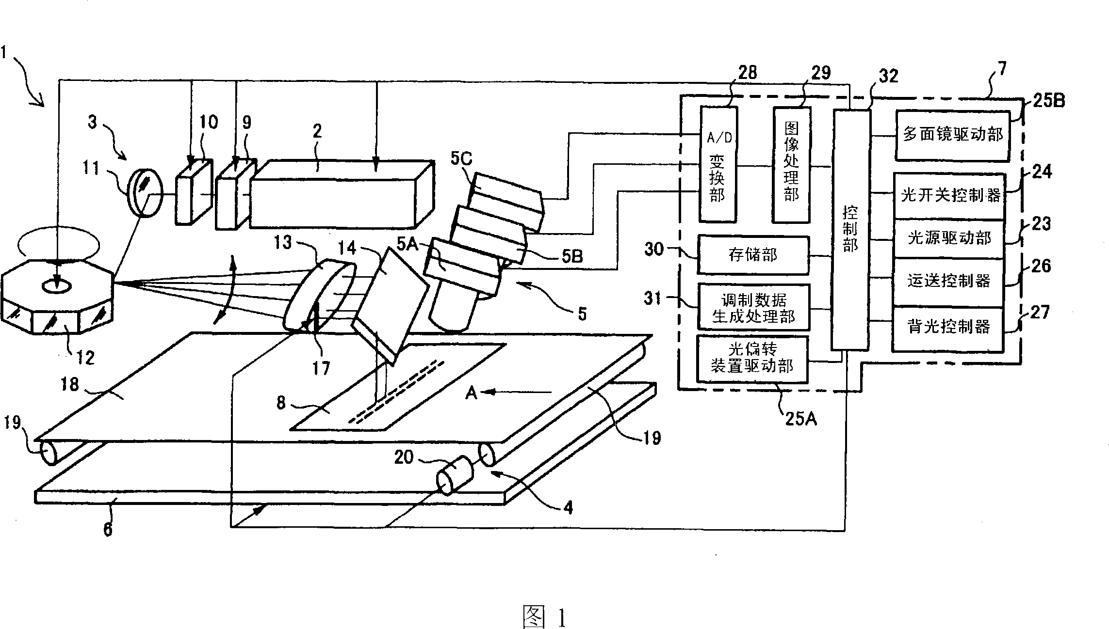
[0038] figure 1 It is a schematic diagram which shows embodiment of the exposure apparatus of this invention. The exposure device 1 exposes a functional pattern on an object to be exposed, and includes a laser light source 2, an exposure optical system 3, a transport device 4, a photographing device 5, a backlight irradiation device 6 as an illumination device, and an optical system control means 7. In addition, the above functional pattern refers to the pattern of the components of the product that are required to perform the original target action. For example, for a color filter, it is a pixel pattern of a black dot matrix or a red, blue, and green color filter. Sheet patterns, and for semiconductor components, wiring patterns or various electrode patterns, etc. In the following description, an example in which a glass substrate for a color filter is used as an ...


PUM


Abstract

An exposure apparatus (1) relatively scans a glass board (8) with laser beams irradiated from an exposure optical system (3) in a direction orthogonally intersecting a shifting direction (arrow A) of the glass board, and exposes a functional pattern at a prescribed pitch on the glass board (8). The exposure apparatus is provided with an image pickup means (5) for picking up an image of a pixel ofa black matrix previously formed on the glass board (8), and an optical system control means (7), which performs a prescribed image process to the pixel image data obtained by the image pickup means (5), a defect is removed from a pixel row image in one scanning area of the laser beams to generate a defect-free pixel row image, detects a reference position of exposure start or completion in the defect-free pixel row image, and controls laser beam irradiation start or irradiation stop of the laser beams, having the reference position as a reference. Thus, alignment accuracy of the functional pattern is improved and cost increase of the exposure apparatus is suppressed.

Description

technical field [0001] The present invention relates to an exposure device for exposing a functional pattern on an object to be exposed. Specifically, a reference position set on a functional pattern previously formed on the object to be exposed and used as a reference is photographed by an imaging device and aligned. The detection is performed, and the start or stop of irradiation of the light beam is controlled based on the reference position to improve the overlapping accuracy of the functional patterns and at the same time try to suppress the cost increase of the exposure device. Background technique [0002] Existing exposure devices use a mask in which a mask pattern corresponding to a functional pattern is preformed on a glass substrate, and copy and expose the above mask pattern on the object to be exposed, for example, a stepper device, a micromirror, etc. Projection (MirrorProjection) device, or close to (Proximity) device. However, in these existing exposure devi...

Claims


Application Information

Patent Timeline
Patent Type & Authority Patents(China)
IPC IPC(8): G03F9/00G03F7/20H01L21/027
CPCG03F7/70383G03F9/7015G03F7/70791
Inventor 伊藤三好
Owner V TECH CO LTD
Why Eureka
Try Eureka