
Sucking apparatus

An adsorption device and adsorption surface technology, applied in transportation and packaging, semiconductor devices, electrical components, etc., can solve the problems of complicated device, increased number of parts, long peeling processing time, etc., to shorten processing time, improve versatility, The effect of preventing adhesion

Inactive Publication Date: 2007-04-11
LINTEC CORP
View PDF1 Cites 5 Cited by
  • Summary
  • Abstract
  • Description
  • Claims
  • Application Information

AI Technical Summary

Problems solved by technology

[0008] However, in the structure of Patent Document 1, the number of components of the structure for moving the shielding plate increases, causing inconvenience that complicates the device
Moreover, since the shielding plate must be moved to hide the dicing tape every time the wafer on the suction surface is replaced, or the shielding plate is retracted to the outside of the suction device, it is inconvenient that the time required for the peeling process of the protective tape becomes longer.
[0009] It is also well known that the dicing tape is kept in an inclined posture by using an elevating device that raises the wafer relative to the ring frame, and the structure that prevents the peeling tape from adhering to the protective tape is also known. Inconvenience resulting in long stripping processing time

Method used


Image

  • Sucking apparatus
  • Sucking apparatus
  • Sucking apparatus

Examples


no. 1 approach

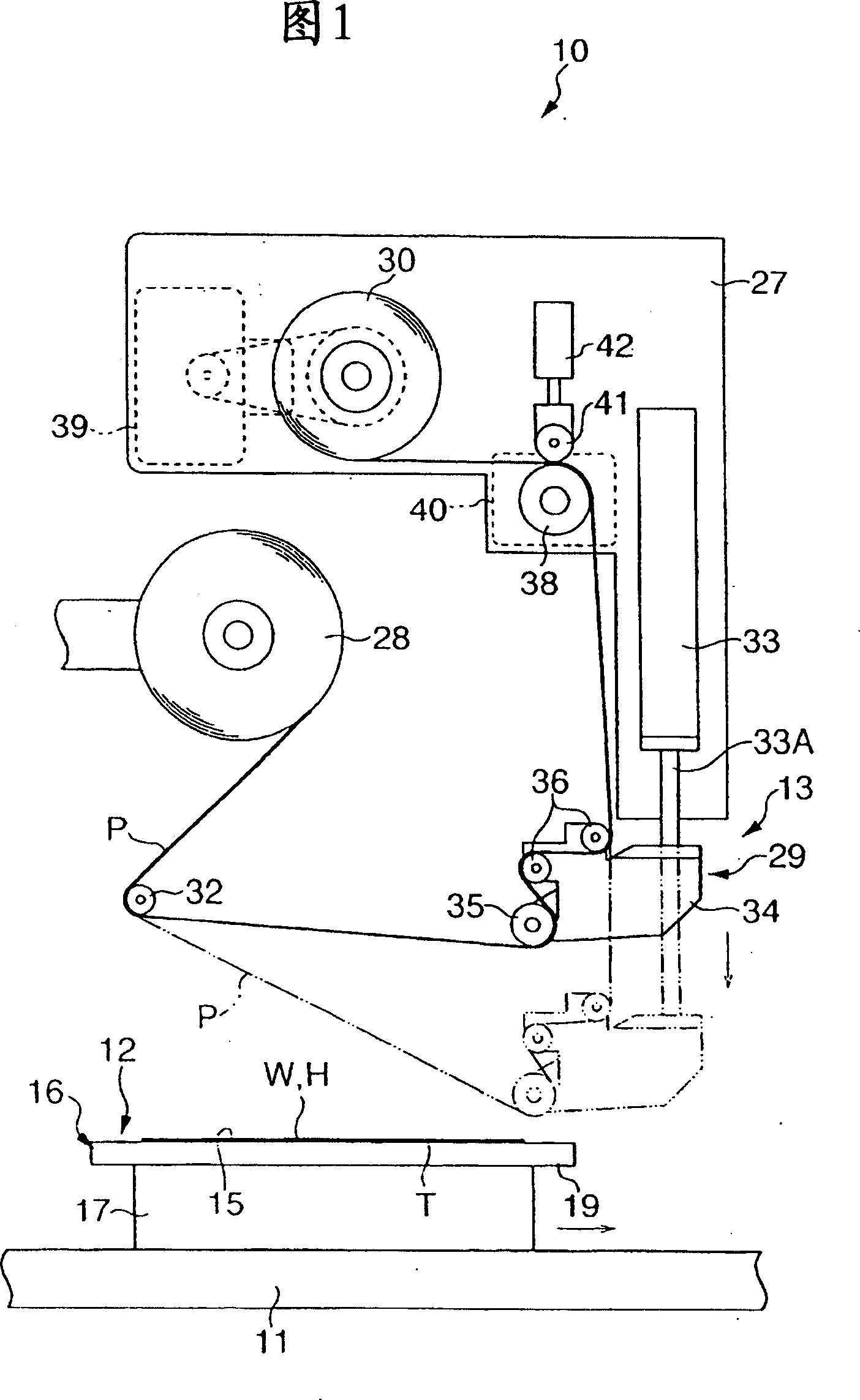
[0049] FIG. 1 shows a schematic configuration diagram of a peeling device using the suction device of the first embodiment. In this figure, the peeling device 10 includes a suction device 12 movably supported via a slider 11 extending in the left-right direction in FIG. 1 , and a peeling device 13 provided above the suction device 12 .

[0050] A wafer W as a plate-shaped member held by the suction device 12 has a substantially disc shape as shown in FIGS. 2 and 3 and is supported on a ring frame R via a dicing tape T as an adhesive sheet. Specifically, the dicing tape T has an adhesive surface T1 on its upper surface, and is stuck to the back surface (lower surface) of the wafer W via the adhesive surface T1. The dicing tape T has a planar area larger than that of the wafer W, and has a planar shape exposed from the outer periphery of the wafer W, and the outer peripheral side is attached to the ring frame R (lower surface). A substantially annular gap S exists between the o...


PUM


Abstract

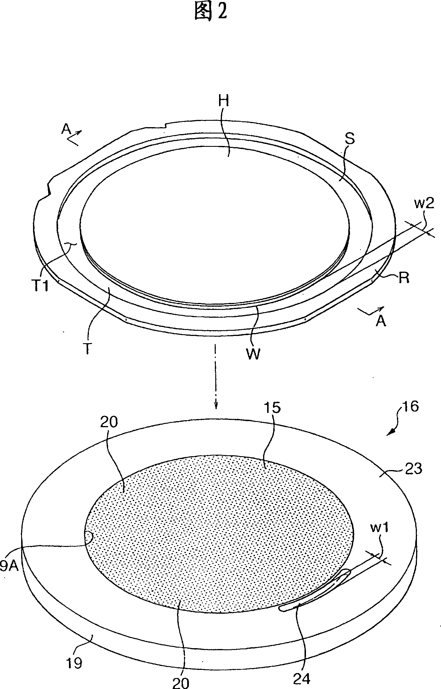
A wafer (W) is supported on a ring frame (R) from a rear side through a dicing tape (T), and a protection tape (H) is adhered on a front side of the wafer. A sucking apparatus (12) is provided with a table (16) having a sucking plane (15) on an upper surface. The sucking plane (15) sucks the dicing tape (T) by prescribed suction to hold the wafer (W). A groove (24) is formed at least in a part of an area along an outer circumference of the sucking plane (15), suction is performed by the sucking plane (15), and the dicing tape (T) is depressed by having the inside of the groove (24) depressurized.

Description

technical field [0001] The present invention relates to a suction device for holding a plate-like member with an adhesive sheet attached to one surface, and more particularly, to a suction device capable of easily and quickly peeling off a protective tape stuck on the other side of the plate-like member . Background technique [0002] Conventionally, a substantially disk-shaped semiconductor wafer (hereinafter simply referred to as a "wafer") is known, in which the circuit surface is formed on the front side. Generally, the thickness of such a wafer is adjusted by cutting the back side with a grinder or the like after attaching a protective tape to the circuit surface. Afterwards, in the state where the back side of the wafer is bonded to the adhesive surface side of the dicing tape exposing the inner side of the ring frame, the protective tape is peeled off from the front side of the wafer, and after that, the wafer is cut into small squares. A semiconductor chip is forme...

Claims


Application Information

Patent Timeline
Patent Type & Authority Applications(China)
IPC IPC(8): H01L21/304H01L21/677H01L21/00H01L21/68H01L21/683
CPCH01L21/6836H01L2221/68395H01L2221/68327H01L21/6835H01L2221/6834H01L2924/3025H01L21/67132Y10T156/1132Y10T156/1168Y10T156/19Y10T156/1944Y10T156/1978H01L21/02H01L21/304
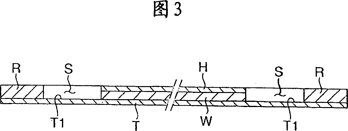
Inventor 小林贤治辻本正树吉冈孝久
Owner LINTEC CORP
Learn More