
Cleaning technology of coarse particles on grinder outlet in water coal slurry manufacturing technology

A production process and technology of coal-water slurry, which is applied in the directions of fuel supply, block/powder fuel preparation, combustion method, etc. Ensures normal and smooth operation, improved accuracy, smooth operation

Inactive Publication Date: 2007-04-18
佛山市南海洁能燃料有限公司
View PDF0 Cites 2 Cited by
  • Summary
  • Abstract
  • Description
  • Claims
  • Application Information

AI Technical Summary

Problems solved by technology

The existing preparation methods of coal water slurry are mill slurry outlet → vibrating screen → buffer box, and some even directly discharge the buffer box from the mill slurry outlet, causing a large amount of coarse particles to enter the buffer box and subsequent processes. It has a great adverse effect on the cleaning of the buffer tank and the use of buffer pumps and slurry filters

Method used


Image

  • Cleaning technology of coarse particles on grinder outlet in water coal slurry manufacturing technology

Examples


Embodiment Construction

[0021] Below in conjunction with embodiment, the present invention is further elaborated:

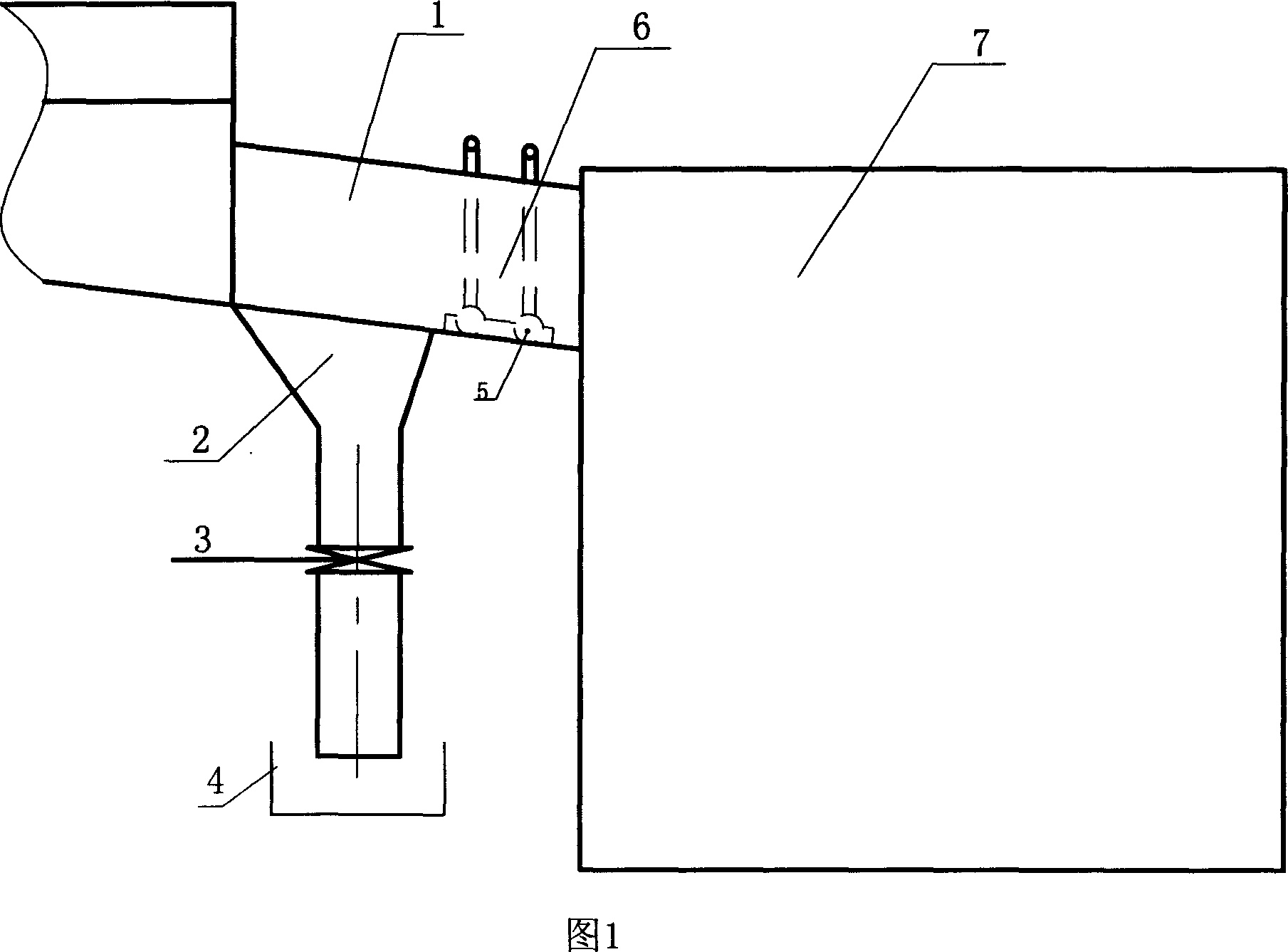
[0022] The concrete steps of the present embodiment are as follows: (seeing as shown in Figure 1)

[0023] 1) Sediment: The coal water slurry enters the special slag removal chute 1 through the vibrating screen, the coarse particles in the slurry including coal particles, iron particles and other impurities enter the chute sediment area 2, and the coal water slurry overflows into the chute magnetic suction area 6 .

[0024] 2) Magnetic attraction: After the coal-water slurry rises and overflows into the magnetic attraction area 6 of the chute, the residual iron slag in the coal-water slurry is absorbed by the permanent magnet 5, and the coal-water slurry enters the buffer tank 7 through the magnetic area.

[0025] 3) Slagging: Coarse particles in the coal-water slurry are deposited in the sediment area for a certain period of time. After the deposition reaches a certain height, the spe...


PUM


Abstract

The invention cleaning technology includes the following steps: settling dregs; magnetic sucking; removing dregs; cleaning dregs; scraping out dregs and recovering waste water. The invention is used for separating coarse particles from coal-water fluid.

Description

Technical field: [0001] The invention belongs to the technical field of coal-water slurry preparation, and in particular relates to a treatment technology in the production process of coal-water slurry, mainly a process for cleaning coarse particles discharged from a mill outlet in the production process of coal-water slurry. Background technique: [0002] The coal-water slurry used as fuel is composed of a mixture of solid coal particles, additives and water in a certain organization. The existing preparation methods of coal water slurry are mill slurry outlet → vibrating screen → buffer box, and some even directly discharge the buffer box from the mill slurry outlet, causing a large amount of coarse particles to enter the buffer box and subsequent processes. It has caused great adverse effects on the cleaning of the buffer tank and the use of the buffer pump and the slurry filter. Invention content: [0003] The purpose of the present invention is to provide a process f...

Claims


Application Information

Patent Timeline
Patent Type & Authority Applications(China)
IPC IPC(8): F23K1/02
Inventor 韩流礼崔志尤邓耀华叶树声
Owner 佛山市南海洁能燃料有限公司
Learn More