
Thermotube and its sealing method

一种热管、封口的技术,应用在间接换热器、照明和加热设备等方向,能够解决热管良率及性能可靠度下降等问题,达到提升机械强度、延长使用寿命、降低泄漏率的效果

Inactive Publication Date: 2007-04-18
FU ZHUN PRECISION IND SHENZHEN +1
View PDF0 Cites 9 Cited by
  • Summary
  • Abstract
  • Description
  • Claims
  • Application Information

AI Technical Summary

Problems solved by technology

However, due to mechanical processing equipment and process technology capabilities, the length of the ineffective end of the heat pipe currently in use is generally 10-15 mm, and if the length of the inactive end increases or decreases by 2-3 mm, ΔT will have a variability of 1-5 ° C, resulting in heat pipe Significant drop in yield and performance reliability

Method used


Image

  • Thermotube and its sealing method
  • Thermotube and its sealing method
  • Thermotube and its sealing method

Examples


Embodiment Construction

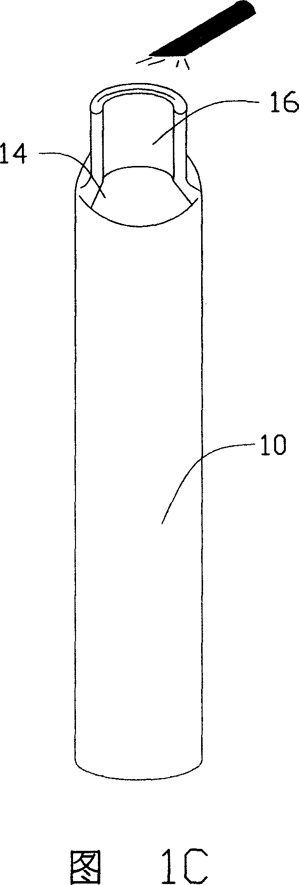
[0015] Please refer to FIGS. 1A to 1D, which are schematic diagrams of the sealing process of the heat pipe of the present invention. The heat pipe sealing process is as follows: a tube body 10 is provided. The tube body 10 includes an open end 12 and a shrinking tube section 14 adjacent to the open end 12 (as shown in Figure 1A). The tube is provided with a capillary structure and filled with an appropriate amount of working fluid. Use a set of flattening dies to stamp the open end 12 to be flattened to form an arc-shaped sealing section 16, as shown in Figure 1B; subsequently, the use of tungsten argon arc welding (TIG) directly The sealing section 16 of the heat pipe is fusion welded at high temperature (as shown in FIG. 1C), so that the shell at the end of the sealing section 16 forms an integral welding section 18. FIG. 1D shows the heat pipe sealing structure manufactured according to the above method, which includes a shrinking tube section 14, a sealing section 16 and a we...


PUM


Abstract

The invention relates to heat pipe. It includes pipe body and filled working fluid. One end of the pipe body is pressed to form a sealing pressing section of which end is formed fusing connecting section by high temperature fusion welding. The sealing method includes the following steps: preparing the pipe body with one open end; pressing; high temperature fusion welding. The invention uses the high temperature fusion welding for the sealing pressing section to make the binding face between the seal and shell disappear and metal shell not be sprung. This can effectively reduce seal leakage rate and heat pipe mechanical void end length, and increase seal mechanical strength to further improve heat pipe reliability and useful life.

Description

【Technical Field】 [0001] The invention relates to a heat pipe and a sealing method thereof. 【Background technique】 [0002] The main manufacturing processes of traditional heat pipes include shrinking tubes, forming capillary structures, welding tail ends, water injection, vacuuming, flattening, cutting, welding... and other complicated processes. [0003] The degree of vacuum in the heat pipe directly affects the response temperature of the phase change latent heat, and the remaining insoluble gas is likely to cause the oxidation of the capillary structure and the heat pipe shell, resulting in a decrease in the performance and reliability of the heat pipe. Therefore, how to ensure the vacuum of the heat pipe is the direction of the relevant industry's efforts. Therefore, methods such as improved water injection vacuuming methods, heating degassing methods, secondary degassing methods, water injection, vacuuming, and welding multi-functional processes have been used, but they all...

Claims


Application Information

Patent Timeline
Patent Type & Authority Applications(China)
IPC IPC(8): F28D15/02B21D41/04
CPCB23P15/26Y10T29/49353F28D15/0283B23P2700/09
Inventor 侯春树李振吉童兆年刘泰健
Owner FU ZHUN PRECISION IND SHENZHEN
Learn More