

Method for regulating photoelectric probe position of high dense CD reading head
A technology of photoelectric detectors and adjustment methods, which is applied to optical detectors, optical recording/reproduction, optical head manufacturing, etc., can solve the problems of troublesome adjustment process and complicated servo circuits, and achieve easy adjustment and positioning accuracy high effect
- Summary
- Abstract
- Description
- Claims
- Application Information
AI Technical Summary
Problems solved by technology
Method used
Image

Examples
Embodiment Construction
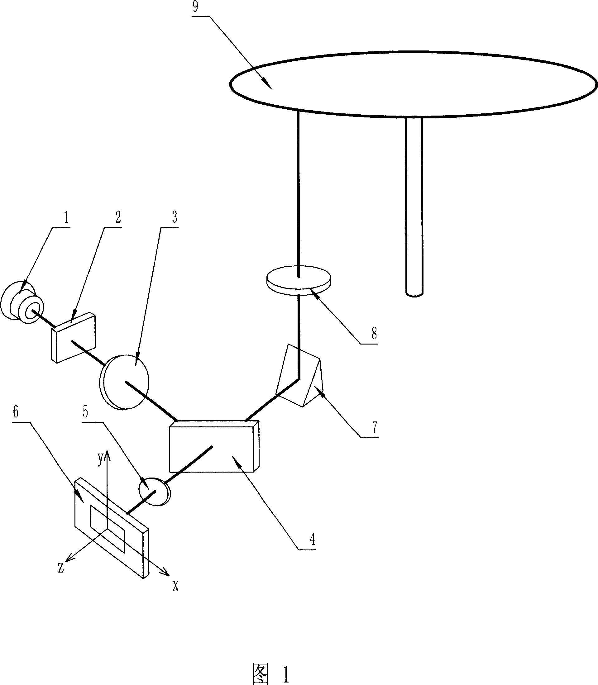
[0022] As shown in Figure 1, an optical path structure of a high-disc optical disc read head includes: a semiconductor laser 1, a grating 2, a collimating mirror 3, a half-transparent mirror 4, a cylindrical mirror 5, a photodetector 6, a reflector Mirror 7, objective lens 8, optical disc 9 and main shaft 10, main shaft 10 is driven by main shaft motor; For the optical path structure of this optical disc reading head, the method for adjusting the photodetector position of high-density optical disc reading head of the present invention, its steps are :
[0023] 1. In the optical path structure of the optical disc reading head, a plane mirror is used to replace the optical disc 9 to ensure that the optical axis of the plane mirror reflection surface and the objective lens 8 are aligned;
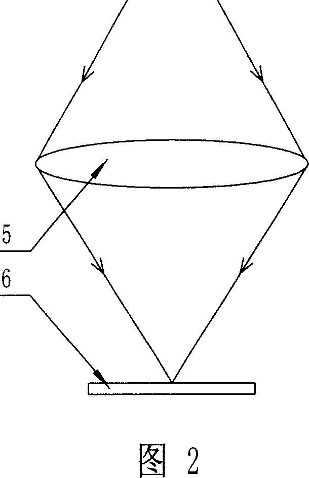
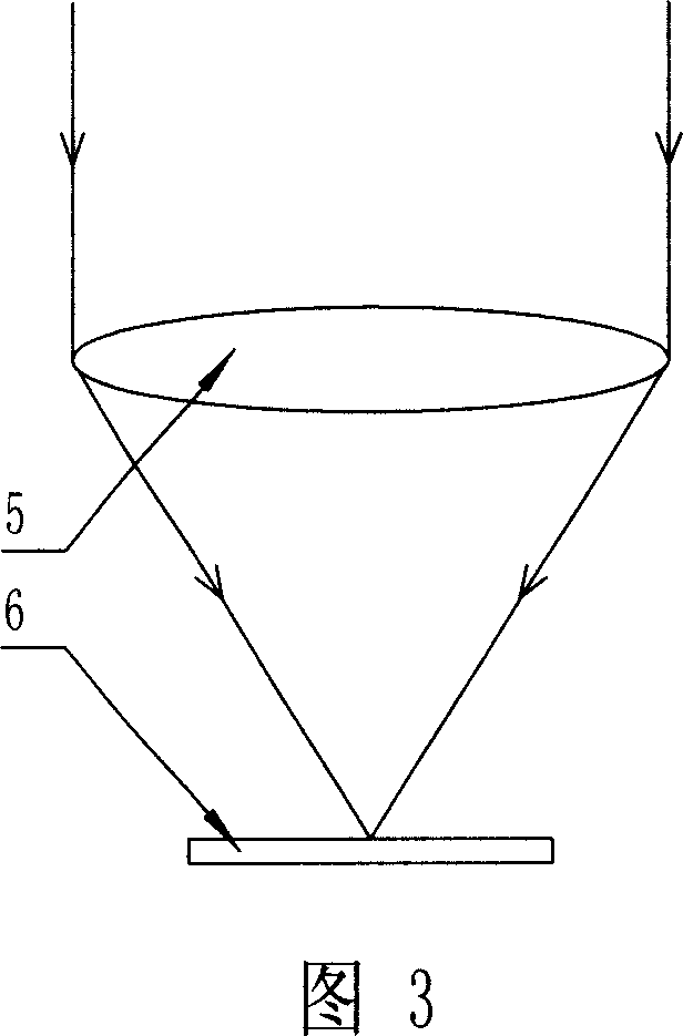
[0024] 2. Remove the cylindrical mirror 5 of the optical disc reading head, adjust the distance between the plane mirror and the objective lens 8 to be the focal length of the objective lens 8,...
PUM
 Abstract
Description
Claims
Application Information