Band stop filter

A technology of band-stop filter and filter, which is applied in the direction of waveguide devices, circuits, electrical components, etc., can solve problems such as large cost factors, and achieve the effects of small intermodulation, good reliability, and reduced number

Inactive Publication Date: 2007-04-18
INTEL CORP
View PDF0 Cites 15 Cited by
  • Summary
  • Abstract
  • Description
  • Claims
  • Application Information

AI Technical Summary

Problems solved by technology

This results in many manual iterative cycles in tuning which means a large cost factor in production

Method used


Image

  • Band stop filter
  • Band stop filter
  • Band stop filter

Examples


Embodiment Construction

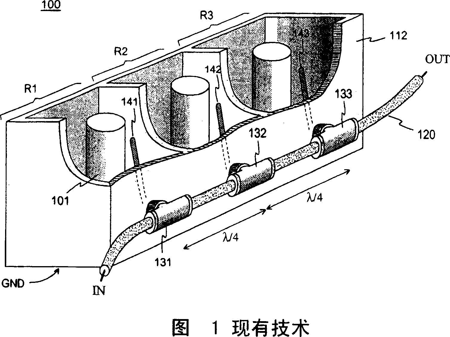
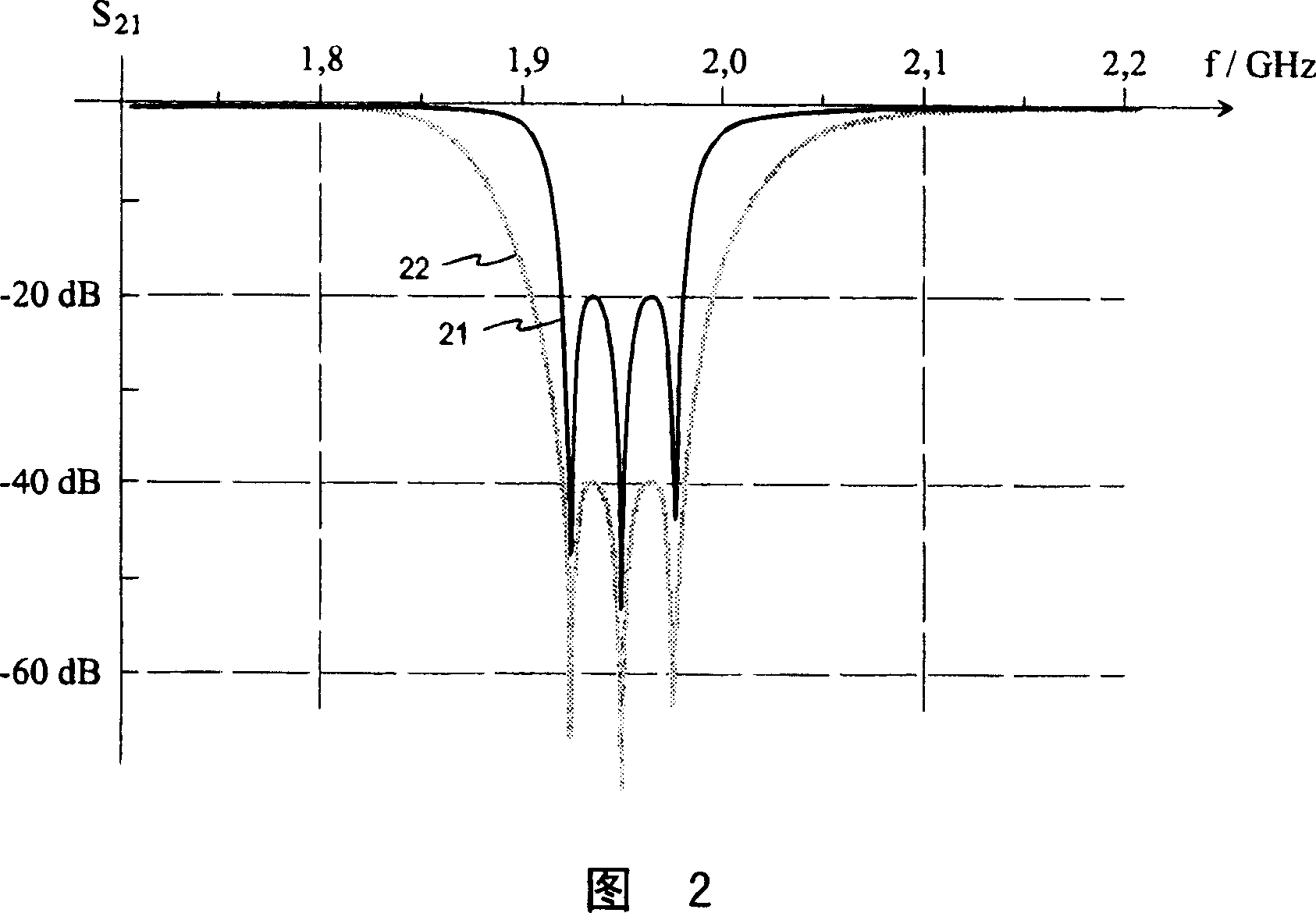
[0018] Figures 1 and 2 have already been explained in the description of the prior art.

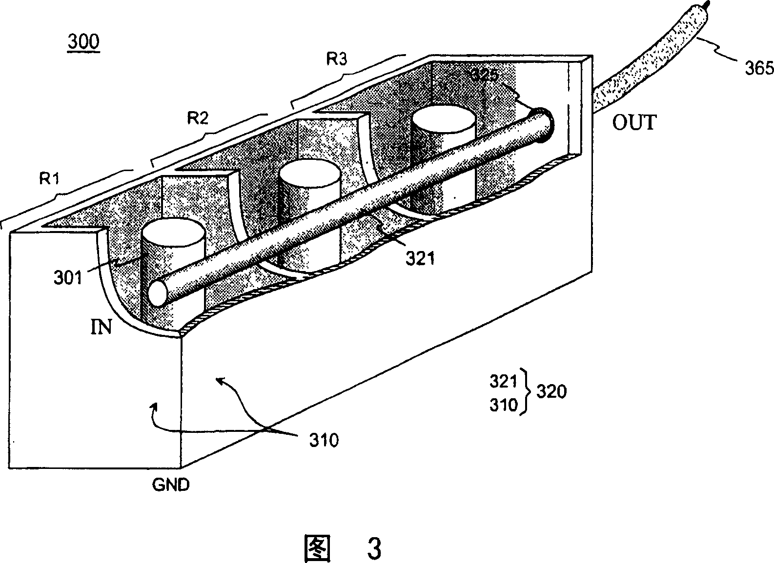
[0019] Fig. 3 shows an example of a band rejection filter according to the present invention. Filter 300 includes coaxial resonators including first R1, second R2, and third R3 in an integral conductive filter housing, like FIG. 1 . The filter housing comprising the bottom, side walls, end walls and cover is shown on FIG. 3 with the cover open so that the inner conductors of the resonators, such as the inner conductor 301 of the first resonator, are partially visible. The inner space of the housing is divided into the resonator cavity by two conductive partitions. The lower end of the inner conductor of the resonator is conductively connected to the bottom of the housing and thus to signal ground GND. Their upper ends have only capacitive coupling to the lid of the housing and the surrounding conductive walls, so the resonators are quarter-wavelength resonators. In addition, the filter...


PUM


Abstract

A band-stop filter (300) implemented by a coaxial resonator for filtering antenna signals in a base station of a mobile communication network. The starting point is a structure with a transmission line and coaxial resonators electromagnetically coupled parallel to it, the natural frequencies of which are slightly different from each other. The resonators (R1, R2, R3) form an integral conductive resonator housing (310), the inner space of which is divided into a resonator cavity by conductive partitions. In the present invention, the center conductor (321) of the transmission line is placed inside the resonator housing such that it passes through all resonator cavities and the housing simultaneously acts as the outer conductor of the transmission line. The resonator cavity is thus part of the cavity of the transmission line. When an electromagnetic field of the same frequency as the resonator's natural frequency is present on the transmission line, the resonator in question starts to oscillate, causing the electromagnetic field to reflect back into the power supply. The strength of the resonance and the width of its area of ​​influence are simultaneously set eg by appropriate selection of the distance of the inner conductor (301) of the resonator from the center conductor (321) of the transmission line. The number of structural components and metal joints in the stopband filter is relatively small. Consequently, less intermodulation occurs in the filter than in corresponding known filters. Other functional units can also be easily incorporated into the structure of the band-stop filter.

Description

technical field [0001] The invention relates to a band-stop filter implemented by a coaxial resonator for filtering antenna signals, in particular in a base station of a mobile communication network. Background technique [0002] In a two-way radio system of a mobile communication network, the transmission and reception frequency bands are relatively close to each other. In particular in full-duplex systems in which signals are transmitted simultaneously in both directions, it must be ensured that a relatively high-power transmission does not disturb the receiver with received or broadband noise of the transmitted blocks. The output signal of the transmitter power amplifier is therefore strongly attenuated in the receive band before being fed to the antenna. A high-pass filter is in principle sufficient for this purpose when the transmit frequency band lies above the receive frequency band. However, if the signals of some other systems whose spectrum is lower than the abov...

Claims


Application Information

Patent Timeline
Patent Type & Authority Applications(China)
IPC IPC(8): H01P1/205H01P1/20H01PH01P1/209
CPCH01P1/209H01P1/2053
Inventor J·普奥三卡里J·阿拉-克乔拉
Owner INTEL CORP
Why Eureka
Try Eureka