Vibration sesor

A vibration sensor and vibrating plate technology, which is applied to electrostatic transducer microphones, instruments, electret electrostatic transducers, etc., can solve problems such as poor assembly, large product performance deviation, and deformation

Inactive Publication Date: 2007-05-02
HOSIDEN CORP
View PDF3 Cites 13 Cited by
  • Summary
  • Abstract
  • Description
  • Claims
  • Application Information

AI Technical Summary

Problems solved by technology

In this case, unless the gap between the weight portion and the restricting member is narrowed, the effect of restricting cannot be sufficiently obtained, and the vibration plate may be damaged or deformed.
However, if the gap is too narrow, the necessary amplitude is also limited, so it is necessary to set the gap with high precision
Therefore, precision is also required at the time of assembly, and as a result, there are problems in that the assemblability is deteriorated, and the performance variation of the product due to assembly errors and the like is also increased.
Therefore, when an excessive impact is applied due to a drop or the like, the possibility of damage to the joint portion between the movable electrode 1 or the fixed portion 11 and the beam 8 increases.
In addition, when an impact is applied to the surface direction of the movable electrode 1, the movable electrode 1 is likely to be displaced, and the beam 8 is likely to be damaged or deformed.

Method used


Image

  • Vibration sesor
  • Vibration sesor
  • Vibration sesor

Examples


Embodiment Construction

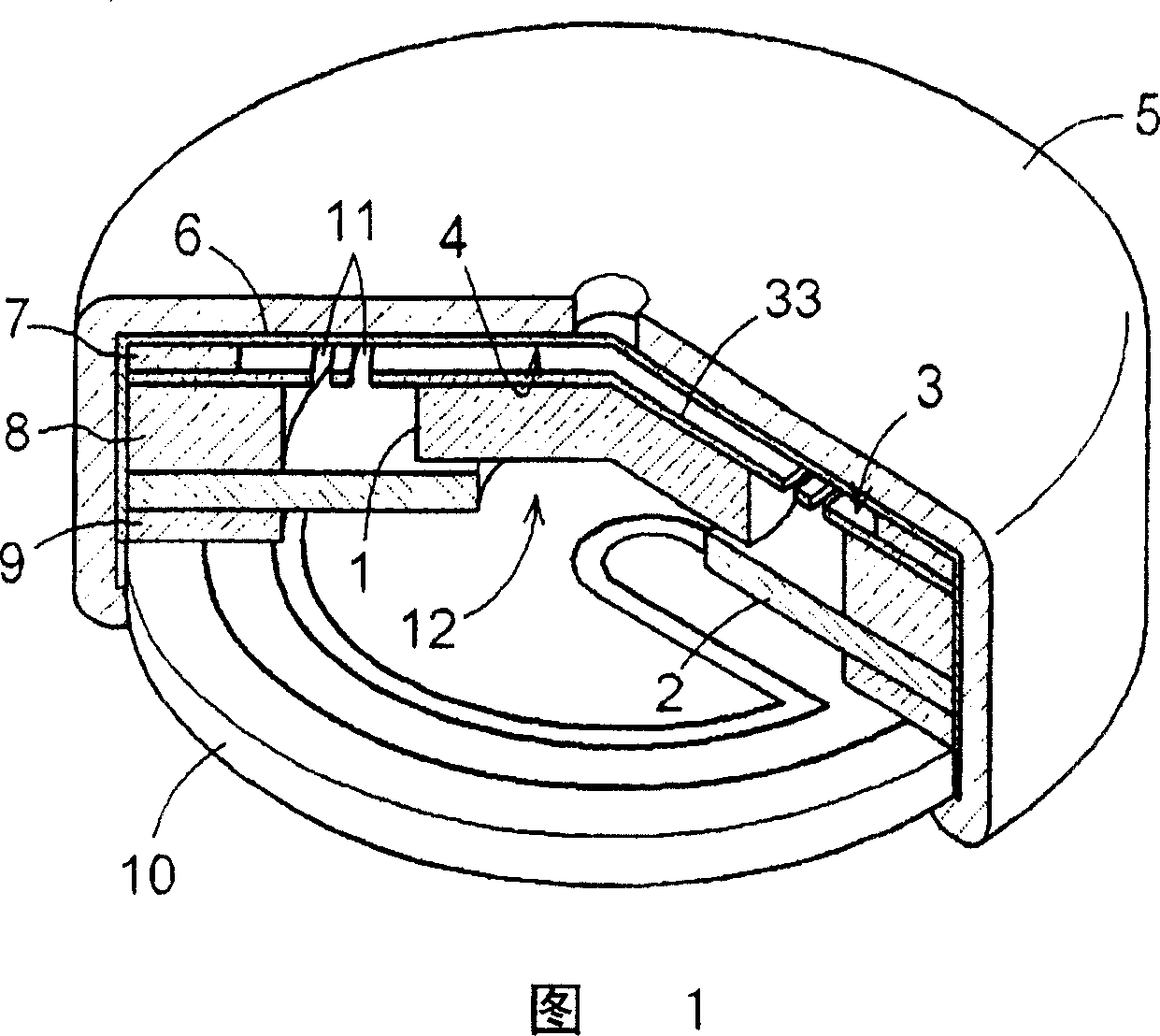
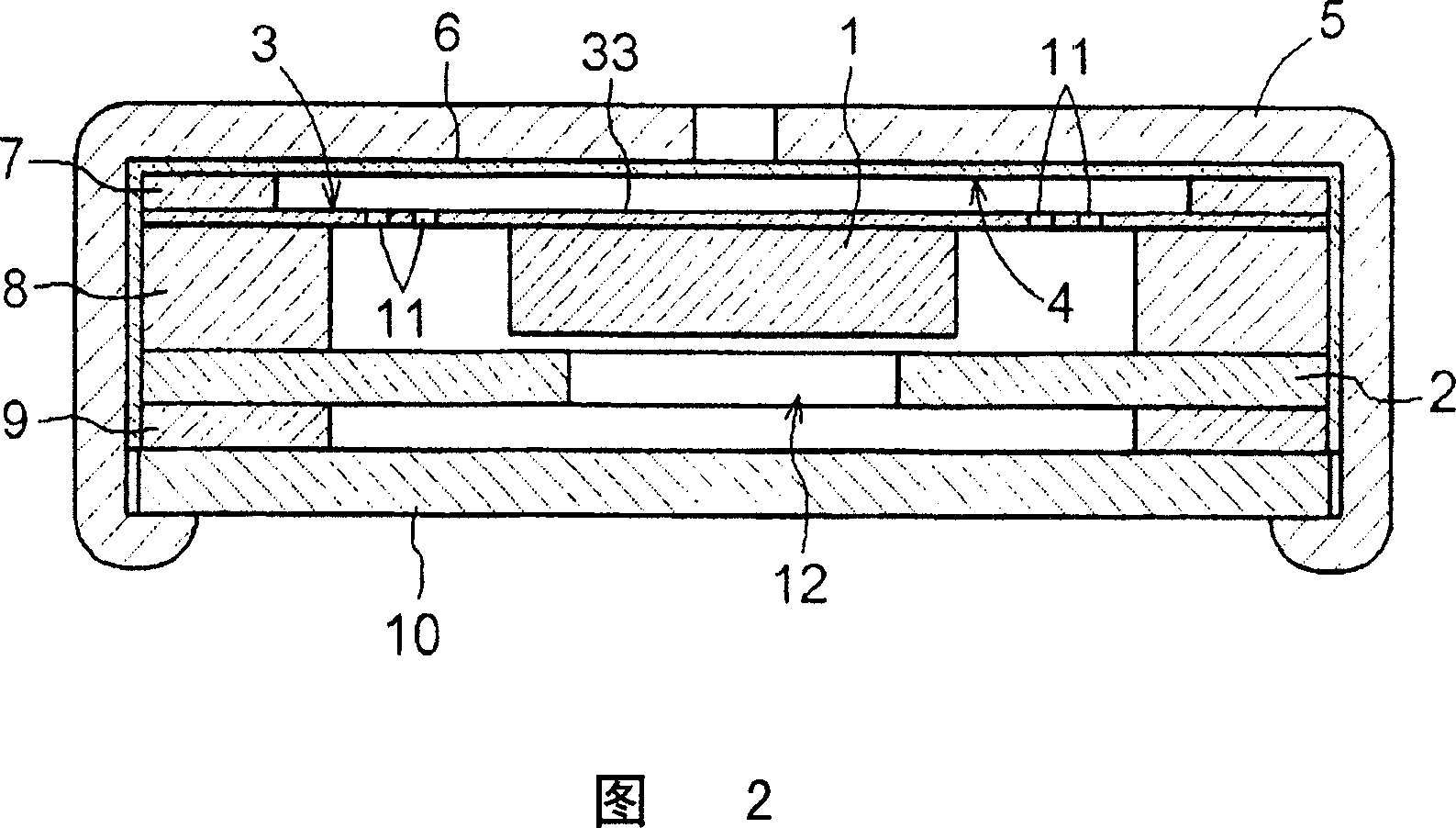
[0032] Hereinafter, embodiments of the present invention will be described based on the drawings. FIG. 1 is a perspective view showing an example of a vibration sensor of the present invention. Fig. 2 is a cross-sectional view of the vibration sensor shown in Fig. 1 . As shown in Fig. 1 and Fig. 2, the vibration sensor of one embodiment of the present invention comprises: fixed electrode 4, is formed with electret layer 6 on the inner surface of casing 5; The surface on which it is placed functions as a vibrating electrode, and the weight portion 1 is provided on the surface opposite to the vibrating electrode. The weight part 1 is displaced in a direction perpendicular to the surface of the vibration plate 3 , and outputs a vibration detection signal based on a change in capacitance between the fixed electrode 4 and the vibration plate 3 . Furthermore, it is comprised so that it may have the restriction plate (restriction member) 2 which contacts the weight part 1, and rest...


PUM


Abstract

A vibration sensor whose impact resistance is improved without reduction in sensitivity. The vibration sensor has a fixed electrode and a vibration plate (3) whose surface facing the fixed electrode functions as a vibration electrode and having a weight (1) on the surface on the opposite side of the vibration electrode, and the vibration sensor outputs a vibration detection signal based on vibration in capacitance between the fixed electrode and the vibration plate (3). The vibration plate (3) is divided by slits (11) into a vibration section (33) that is positioned at the central section of the plate and has the weight (1), a fixed section (31) that is positioned on the periphery of the plate and fixes the vibration plate (3), elastic supporting sections (32) that each have narrow central section (32c) and that are formed at equal intervals in the circumferential direction to connect the vibration section (33) and the fixed section (31). Further, the slits (11) are provided at equal intervals in the circumferential direction such that the end sections on the vibration plate (33) side of and the end sections on the fixed section (31) side of adjacent slits (11) are superposed on each other in the radical direction.

Description

technical field [0001] The present invention relates to a vibration sensor having a fixed electrode and a surface facing the fixed electrode functioning as a vibration electrode, a vibration plate having a weight portion on a surface opposite to the vibration electrode, based on the above fixed electrode and the above vibration sensor. A vibration detection signal is output based on a change in electrostatic capacitance between the plates. Background technique [0002] An electrostatic capacitance detection type, that is, an electret condenser microphone (hereinafter referred to as ECM) type vibration sensor is widely used in various applications such as a microphone and a pedometer. Patent Document 1 described below discloses a technology of an earphone that detects bone conduction vibration. This document shows a method of adding a weight (weight part) to a movable electrode (equivalent to a vibration plate) to substantially increase the movable The mass of the electrode...

Claims


Application Information

Patent Timeline
Patent Type & Authority Applications(China)
IPC IPC(8): G01H11/06G01P15/125H04R19/01G01H11/08H04R19/04
CPCH04R19/04G01H11/06G01P15/125G01P2015/084
Inventor 安田护杉森康雄
Owner HOSIDEN CORP
Why Eureka
Try Eureka