Dust collection box and steam vacuum cleaning machine using the same

A technology for vacuum cleaning and dust collection box, applied in the field of dust collection box, can solve the problems of unreasonable layout, steam inhalation, inconvenient use of wires, etc., and achieve the effect of preventing splashing or reverse flow, preventing splashing and reverse flow, and improving the filtering effect.

Inactive Publication Date: 2007-05-09
韩京姬
View PDF0 Cites 2 Cited by
  • Summary
  • Abstract
  • Description
  • Claims
  • Application Information

AI Technical Summary

Problems solved by technology

[0002] In the prior art, the vacuum motor of the steam vacuum cleaning machine is installed in the base. When a motor with a large capacity is used to increase the vacuum suction rate, the height of the entire base will rise, making it difficult to clean the underside such as bed boards and sofas; Moreover, the dust collection channel is also located in the base, resulting in a complicated internal structure of the base
[0003] There is no cord reel installed on the existing steam vacuum cleaner, so it is inconvenient to use the cord
[0004] At the same time, when steam cleaning and vacuum cleaning are performed at the same time with the existing steam vacuum cleaner, the steam will be sucked into the motor, causing a short circuit accident
[0005] On existing steam vacuum cleaners, the wire strips for the switch, motor and heater are located on the outside, so it looks unsightly and dangerous
[0006] In this way, there is a problem that the steam vacuum cleaner is inconvenient to use due to unreasonable layout in the existing steam vacuum cleaner

Method used


Image

  • Dust collection box and steam vacuum cleaning machine using the same
  • Dust collection box and steam vacuum cleaning machine using the same
  • Dust collection box and steam vacuum cleaning machine using the same

Examples


Embodiment Construction

[0077] The following are examples to illustrate the present invention with reference to the accompanying drawings.

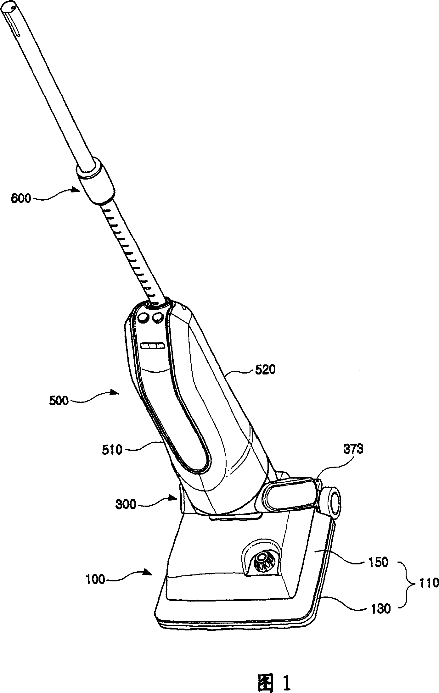
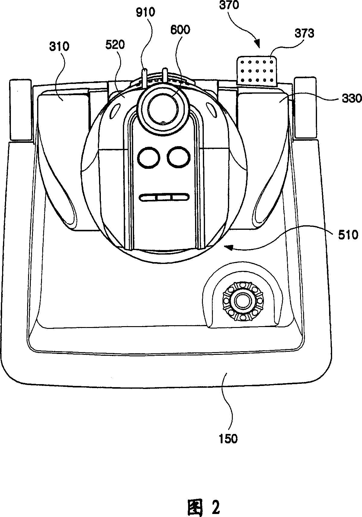
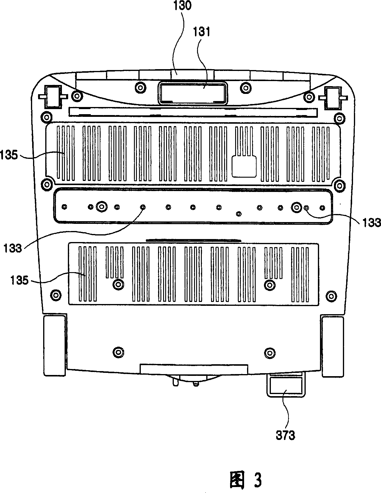
[0078] 1 is a front perspective view of a steam vacuum cleaner according to an example of the present invention, and FIGS. 2 to 4 are a plan view, a bottom view and a rear view of FIG. 1 .

[0079] As shown in FIG. 1 and FIG. 4 , the steam vacuum cleaner in this example is generally composed of a base 100, an operating body 500, and a neck 300 connecting the base 100 and the operating body 500. At the same time, the operating body There should be a handle bar 600 with an adjustable length on the 500, and the handle bar 600 is detachably mounted on the tube 550 to be described below.

[0080] As shown in FIG. 5 , the base 100 is composed of a main body 110 composed of a bottom plate 130 and an upper cover 150 , a steam generating part 170 mounted on the bottom plate 130 , and a dust collecting box 200 mounted on the back of the main body 110 .

[0081] As shown ...


PUM


Abstract

A dust collection box is provided for comprising a dust collection housing which has an inlet orifice and an outlet orifice, an inlet chamber which is arranged inside the dust collection housing and connects with the inlet orifice, an outlet chamber which is arranged inside the dust collection housing and connects with the outlet orifice, a separating wall arranged inside the dust collection housing dividing the inlet chamber from the outlet chamber, a filter means which is provided to open or close the dust collection housing on the upper of the housing and filter the air in the inlet chamber which is supplied to the outlet chamber. The dust collection box provided in this invention is comprised of a dust collection housing having an inlet orifice and an outlet orifice, an inlet chamber and an outlet chamber arranged inside the housing, a separating wall for dividing the inlet chamber and outlet chamber, a filter means for filtering the air in the inlet chamber and supplying the filtered air to the outlet chamber. By applying this structure of present invention, splash or backflow of dust or water can be well prevented.

Description

technical field [0001] The invention relates to a steam vacuum cleaning machine and a dust collecting box used therein. Background technique [0002] In the prior art, the vacuum motor of the steam vacuum cleaning machine is installed in the base. When a motor with a large capacity is used to increase the vacuum suction rate, the height of the entire base will rise, making it difficult to clean the underside such as bed boards and sofas; Moreover, the dust collection channel is also arranged in the base, which causes the internal structure of the base to be very complicated. [0003] There is no electric wire reel installed on the existing steam vacuum cleaner, so it is very inconvenient to use the electric wire. [0004] Also, when steam cleaning and vacuum cleaning are performed simultaneously with an existing steam vacuum cleaner, steam is sucked into the motor, causing a short-circuit accident. [0005] The wires for connecting the switch, the ...

Claims


Application Information

Patent Timeline
Patent Type & Authority Applications(China)
IPC IPC(8): A47L9/10A47L5/12A47L7/06A47L11/34
CPCA47L11/26A47L11/4044A47L11/4094
Inventor 韩京姬
Owner 韩京姬
Why Eureka
Try Eureka