
Flame straightening in a furnace

一种火焰、炉子的技术,应用在燃烧类型、照明和加热设备、非催化热裂化等方向,能够解决不能消除等问题

Active Publication Date: 2007-05-09
AIR PROD & CHEM INC
View PDF2 Cites 10 Cited by
  • Summary
  • Abstract
  • Description
  • Claims
  • Application Information

AI Technical Summary

Problems solved by technology

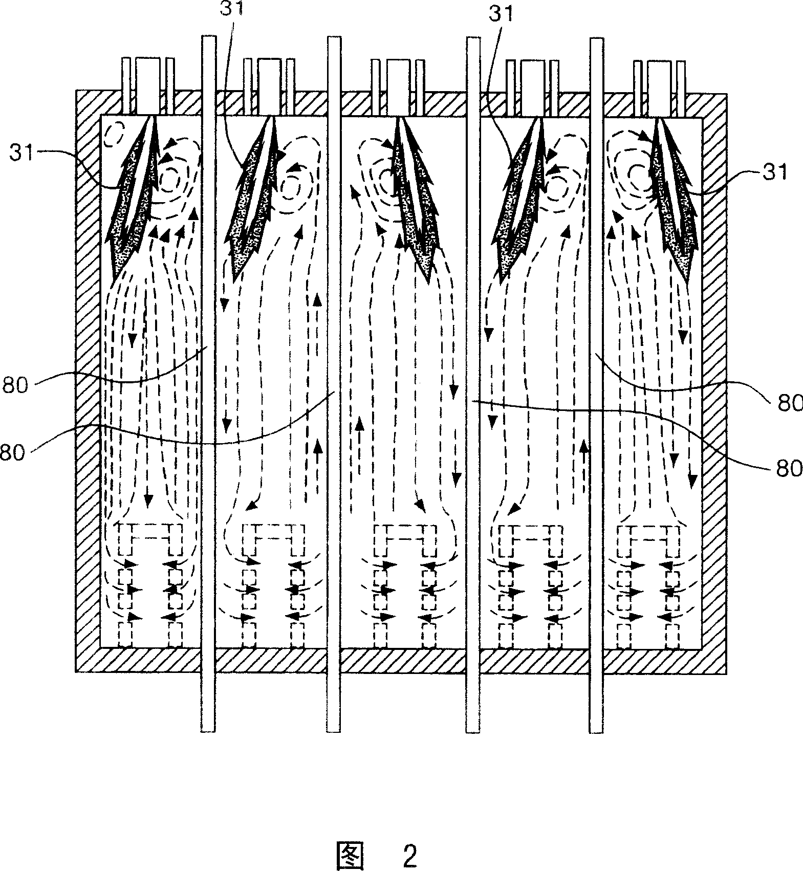
These methods do not eliminate the problems associated with the furnace gases that the flame interacts with

Method used


Image

  • Flame straightening in a furnace
  • Flame straightening in a furnace
  • Flame straightening in a furnace

Examples


Embodiment Construction

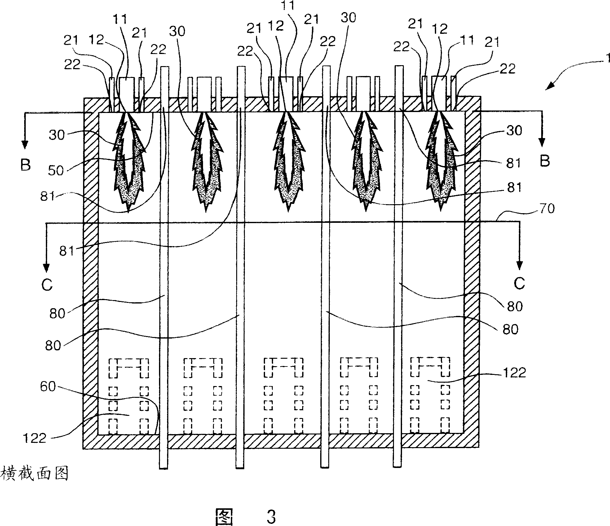
[0038] In one embodiment of the invention, the invention relates to a method of generating a straightening flame in a furnace. Referring to FIG. 3, which illustrates a cross-sectional view of the furnace 1, the method of the present invention includes introducing an oxidant into a plurality of oxidant pipes 11. The oxidant includes oxygen, and may additionally include fuel and / or combustion products. The oxidant may be air. The oxidant may include at least 10% oxygen by volume. The oxidant can be formed by pre-combustion of fuel and air in the pre-burner and is introduced through the oxidant pipe. The oxidant can be at ambient temperature or can be heated above ambient temperature.

[0039] The oxidant pipe 11 has an outlet 12 fluidly connected to the inside of the furnace 1, wherein the outlet 12 is closest to the inner end 50 of the furnace 1. The oxidant outlet 12 may be flush with the inner end 50. As shown in FIG. 3, the furnace 1 also has an inner end 60 opposite to the inne...


PUM


Abstract

The present invention relates to a method and furnace for generating straightened flames in a steam methane reformer or ethylene cracking furnace where fuel-staged burners are used. Fuel staging may be used for reducing NOx emissions. Criteria for generating straightened flames are provided. These criteria relate to oxidant conduit geometry and furnace geometry. Techniques for modifying the furnace and / or burners to achieve these criteria are also provided.

Description

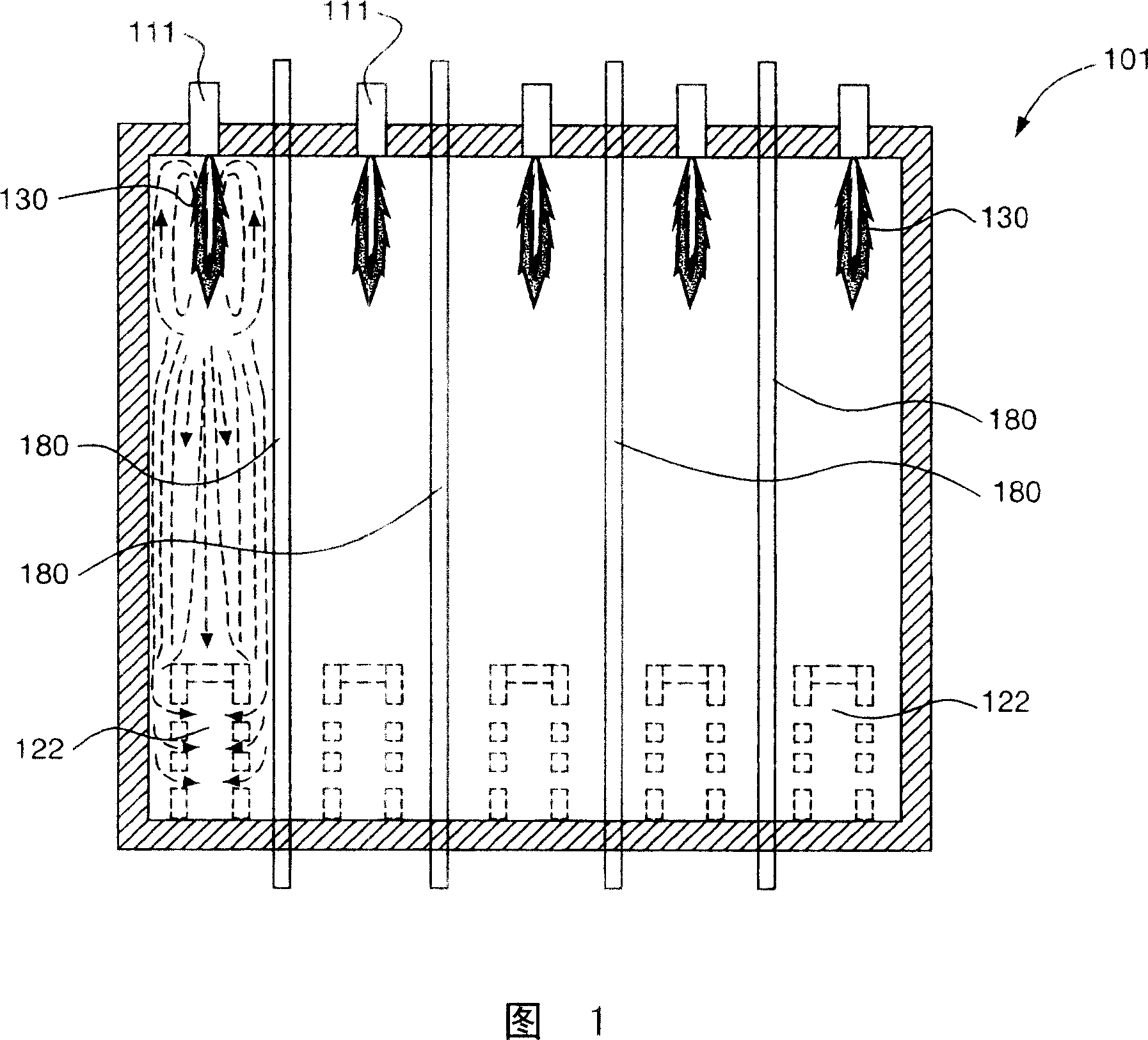
Technical field [0001] The invention relates to a method and a furnace for generating a straightening flame in a furnace, in particular to a top-fired and bottom-fired furnace with multiple rows of reaction chambers (such as process tubes) and multiple rows of low-NOx burners Methods and furnaces for generating corrective flames. Background technique [0002] Large top-fired and bottom-fired multi-row furnaces (such as reforming furnaces and ethylene cracking furnaces) have complex gas flow patterns in the furnace. Undesirable gas flow patterns can deflect the flame and cause local overheating of the process tube, thus affecting the performance of this furnace. [0003] Fig. 1 shows a conventional steam methane reformer 101 with a top-fired structure. The raw material gas (steam+natural gas) is supplied from the top of the process pipe 180 filled with the reforming catalyst. The feed gas is reformed in the process tube 180 filled with catalyst to form synthesis gas (mainly H 2 , ...

Claims


Application Information

Patent Timeline
Patent Type & Authority Applications(China)
IPC IPC(8): C01B3/38
CPCF23C5/08B01J8/062C01B3/384C01B2203/0233C01B2203/0816C10G9/20F23C6/02F23C2201/102F23C2201/30F23C2900/03002F23C2900/05081F23D14/22F23D14/46F23D14/00
Inventor M·L·乔施X·J·李W·R·李克特A·G·斯拉维杰科夫S·P·老迪马蒂诺
Owner AIR PROD & CHEM INC
Learn More