Coal liquefaction complex with minimal carbon dioxide emissions

a technology of carbon dioxide emission and coal liquefaction complex, which is applied in the direction of hydrogen/synthetic gas production, energy input, hydrogen, etc., can solve the problems of low thermal efficiency, low cost, and low economic benefits of coal liquefaction, and achieve the effect of enhancing oil recovery and reducing carbon dioxide emissions from the plan

Active Publication Date: 2014-03-18
INST FR DU PETROLE
View PDF6 Cites 8 Cited by
  • Summary
  • Abstract
  • Description
  • Claims
  • Application Information

AI Technical Summary

Benefits of technology

[0017]The invention described herein relates to processes that combine the pre-combustion, capture of carbon dioxide with production of a hydrogen-rich fuel source within a facility treating carbonaceous material by liquefaction (often called in the text CBTL facility i.e. Carbon and / or Biomass to Liquids conversion facility) to drastically reduce the carbon dioxide emissions from the plant. The hydrogen-rich fuel is utilized for the process fired heaters and the fuel quality (carbon content) can be set to meet the refinery's CO2 emissions objectives. Moreover, the CO2 captured can be sequestered and / or utilized for enhanced oil recovery (EOR).
[0037]The process can also be described as an improved process for reducing the carbon dioxide emissions of a CBTL facility wherein the improvement comprises utilizing a steam methane reformer complex comprising a steam methane reformer reactor and furnace, a water gas shift unit, a carbon dioxide capture unit, and a hydrogen purification unit, to provide hydrogen to the process fired heaters as well as for other upstream process needs, said steam reformer reactor unit fed by fuel sources from upstream processes.

Problems solved by technology

However, after World War II, crude oil was widely available at reasonable prices and the implementation of coal liquefaction was therefore not commercially attractive.
As a result, only a small quantity of liquid fuels sold today is produced using a coal liquefaction process.
While commercially demonstrated, the ICL technologies are very complex, capital intensive, and have low thermal efficiencies compared to direct coal liquefaction.
The DCL technologies demonstrated commercial readiness, however, no commercial projects proceeded as oil prices fell and oil supplies increased.
Although technology exists for capturing the dilute CO2 from this stream, it is highly capital intensive and not practiced commercially.
However, this configuration requires a recycle of CO2 to the furnace to moderate the resulting temperature and also results in high investment and operating costs primarily related to the air separation plant and is not economically practical.
However, significant CO2 emissions remain from the plant fired heaters and steam boiler where tail gas, plant fuel gas, imported natural gas or fuel oil are used as fuel.

Method used


Image

  • Coal liquefaction complex with minimal carbon dioxide emissions
  • Coal liquefaction complex with minimal carbon dioxide emissions
  • Coal liquefaction complex with minimal carbon dioxide emissions

Examples


case 1

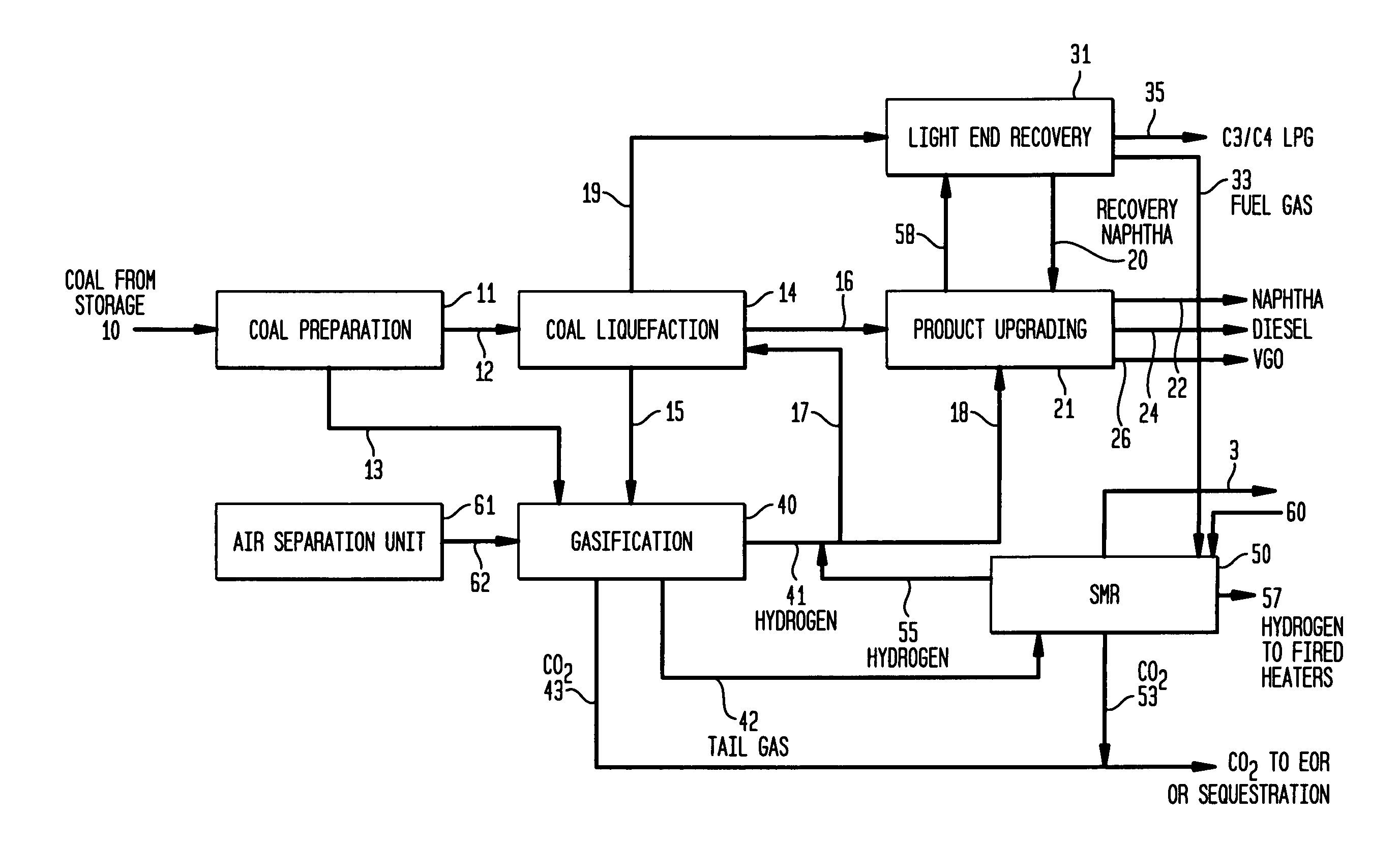
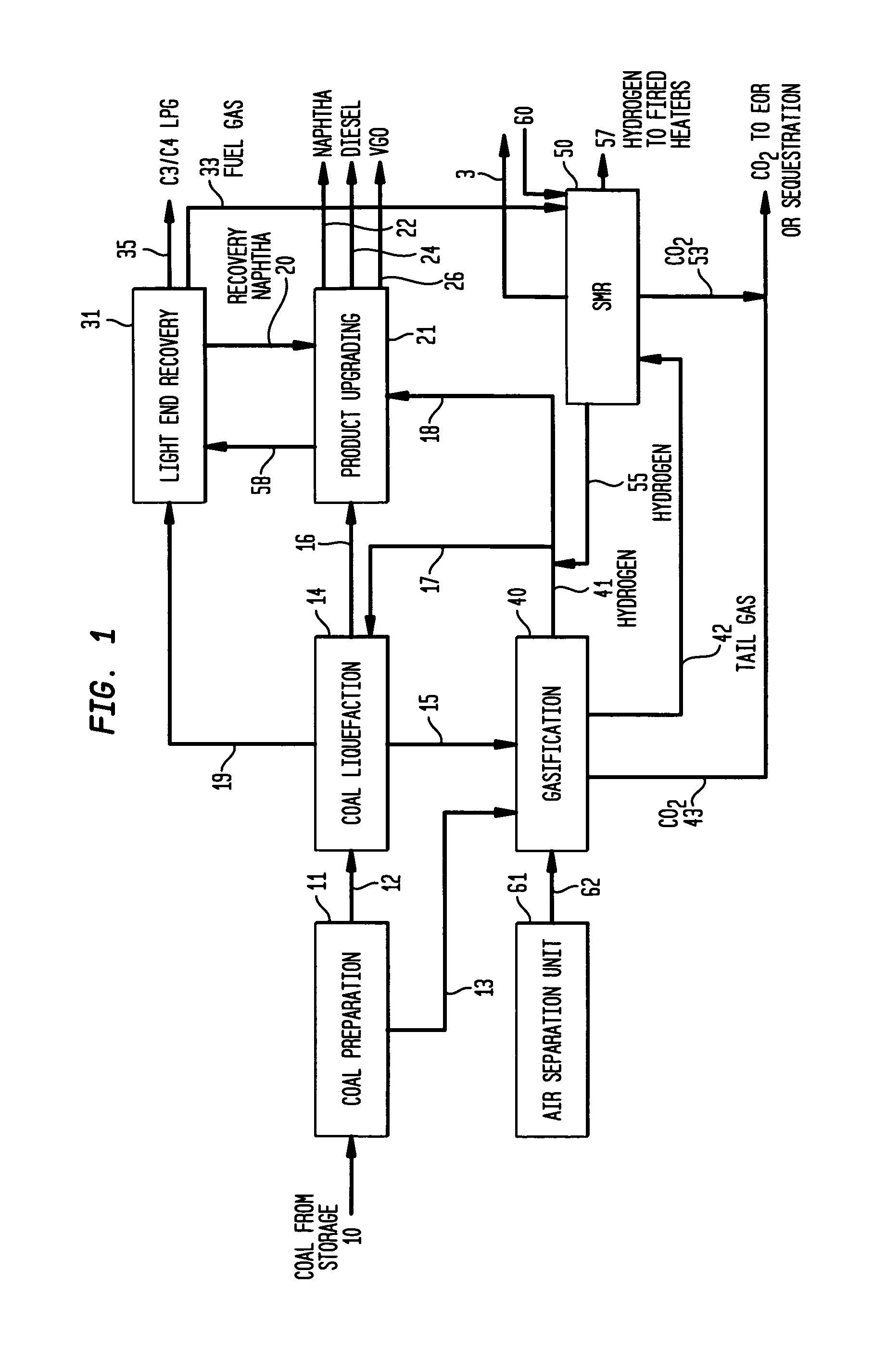
[0062]The unconverted coal, heavy liquefaction residue and supplemental coal are fed to a gasification plant to provide plant hydrogen. Fuel gas is produced from the H-CoalTS Unit, secondary hydroprocessing units and the gasification PSA tail gas.

[0063]In the pre-invention case, CO2 capture is utilized in the gasification plant to attain approximately 87% capture of the total CO2 produced in the gasification plant and 75% of the total liquefaction facility. The plant fired heaters are fueled by a blend of the gasifier tail gas and process generated fuel gases. There is no SMR Unit in the pre-invention case with all hydrogen generated via gasification of the H-Coal bottoms and supplemental coal. A summary of the key plant inputs and products is shown in Table 1. As shown in the table, the pre-invention case requires 1,972 STPD of supplemental coal feed to gasification to provide the total plant hydrogen requirements (224 MM SCFD). The total CO2 emitted to the atmospheric is 2,847 STP...

case 2

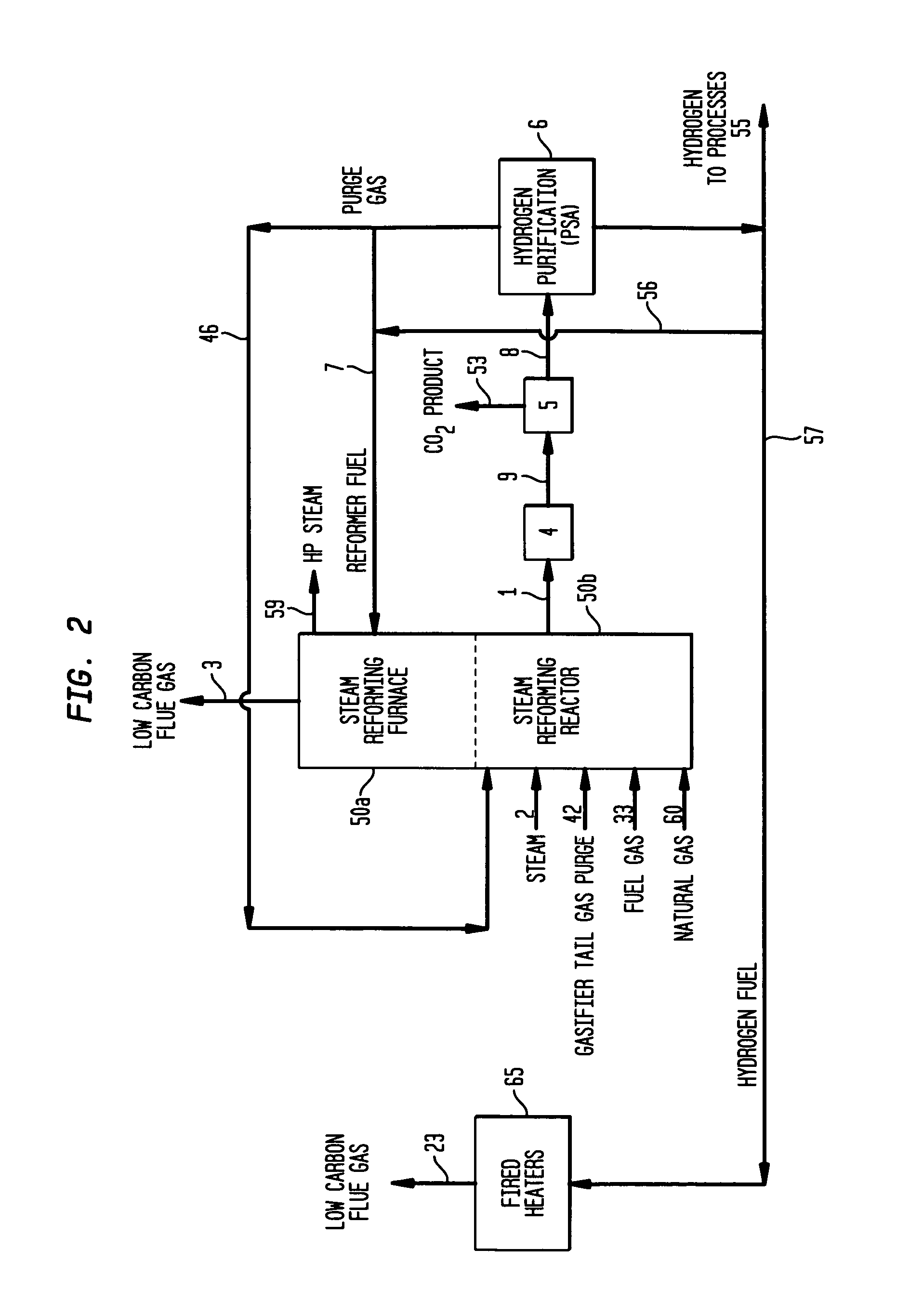
[0064]In the case that utilizes Applicant's invention, a SMR Unit is added to process fuel gas from the plant, tail gas purge from the pressure swing absorber unit in the gasification complex, and tail gas from the pressure swing absorber unit that is part of this SMR unit to produce hydrogen and capture the CO2 produced

[0065]The SMR furnace is fed by SMR produced hydrogen and a small quantity of the SMR PSA tail gas. Details of the invention case SMR Unit operation are shown in Table 2. As shown in the table, 137.5 MM SCFD of hydrogen (99.9 V % purity) is produced in the SMR Unit. This hydrogen is used as follows: 55.0 MM SCFD to the SMR furnace, 55.6 MM SCFD to the liquefaction complex fired heaters (in place of fuel gas), and 26.9 MM SCFD to process plants including the liquefaction reactors. The latter hydrogen reduces that required from the gasifier and results in lower supplemental coal required. As shown in Table 1, the supplemental coal to the gasifier is reduced from 1,972 ...


PUM

PropertyMeasurementUnit
volume percentaaaaaaaaaa
temperaturesaaaaaaaaaa

Abstract

The invention described herein relates to a novel process for reducing the carbon dioxide emissions from a coal and / or biomass liquefaction facility by utilizing a steam methane reformer unit in the complex designed to produce additional hydrogen which can be thereafter utilized in the process, as required for the plant fired heaters (including the SMR furnace), and for the production of plant steam. The plant light ends (C1, C2, etc.), which are normally utilized as fuel gas streams are the primary feeds to the SMR Unit along with the tail gas purge from a gasification complex within the facility.

Description

FIELD OF THE INVENTION[0001]Climate change concerns have increased awareness over the level of carbon dioxide (CO2) emissions from various refinery processes and facilities which convert low-valued hydrocarbons to more useful fuels. Applicants disclose an efficient and effective technique for reducing the carbon dioxide emissions from a coal and / or biomass to liquids facility (CBTL) by capturing the carbon dioxide in a centralized facility and providing fuel gas low in carbon to process fired heaters, which account for a high percentage of carbon emissions at a typical CBTL facility.BACKGROUND OF THE INVENTION[0002]The two primary approaches for coal refining for the purpose of converting coal to liquid fuels are called direct and indirect coal liquefaction. Direct coal liquefaction (DCL) reacts coal in a solvent with hydrogen at high temperature and pressure to produce liquid fuels. DCL was first developed in Germany in 1913 and used commercially in Germany between 1927 and 1945. H...

Claims


Application Information

Patent Timeline
Patent Type & Authority Patents(United States)
IPC IPC(8): B01D53/14C10G1/06C01B32/50
CPCC01B2203/0827C10J2300/1612B01D2257/504B01D53/047C01B3/384C10J2300/093C10G1/06B01D2256/12C01B2203/0475B01D2256/16C10J3/00C01B2203/0415C10J2300/0959C10K1/32C01B2203/062C10K1/004C10K1/143C01B2203/86C10G2300/4043B01D53/62Y02C10/04C10K3/04B01D2257/102Y02C10/06C10K1/024C01B3/48C01B2203/1235C01B2203/0233C01B2203/043C10J2300/16C10K1/08C01B2203/0283C10J2300/1678C01B2203/0405C10K1/005C10J2300/0969Y02C20/20Y02E20/18Y02P20/129Y02P20/151Y02P30/00Y02P30/40Y02C20/40
Inventor COLYAR, JAMES J.MACARTHUR, JAMES BPELUSO, MICHAEL
Owner INST FR DU PETROLE
Why Eureka
Try Eureka