Target material and its use in a sputter process

A target material and absorbing layer technology, applied in the field of target materials, can solve problems such as coating peeling and bubble formation, and achieve the effects of long service life, increased sputtering rate, and high scratch resistance

Inactive Publication Date: 2007-05-09
APPLIED MATERIALS INC
View PDF4 Cites 4 Cited by
  • Summary
  • Abstract
  • Description
  • Claims
  • Application Information

AI Technical Summary

Problems solved by technology

However, the problem encountered is that the coating peels off or bubbles form

Method used


Image

  • Target material and its use in a sputter process
  • Target material and its use in a sputter process
  • Target material and its use in a sputter process

Examples


Embodiment Construction

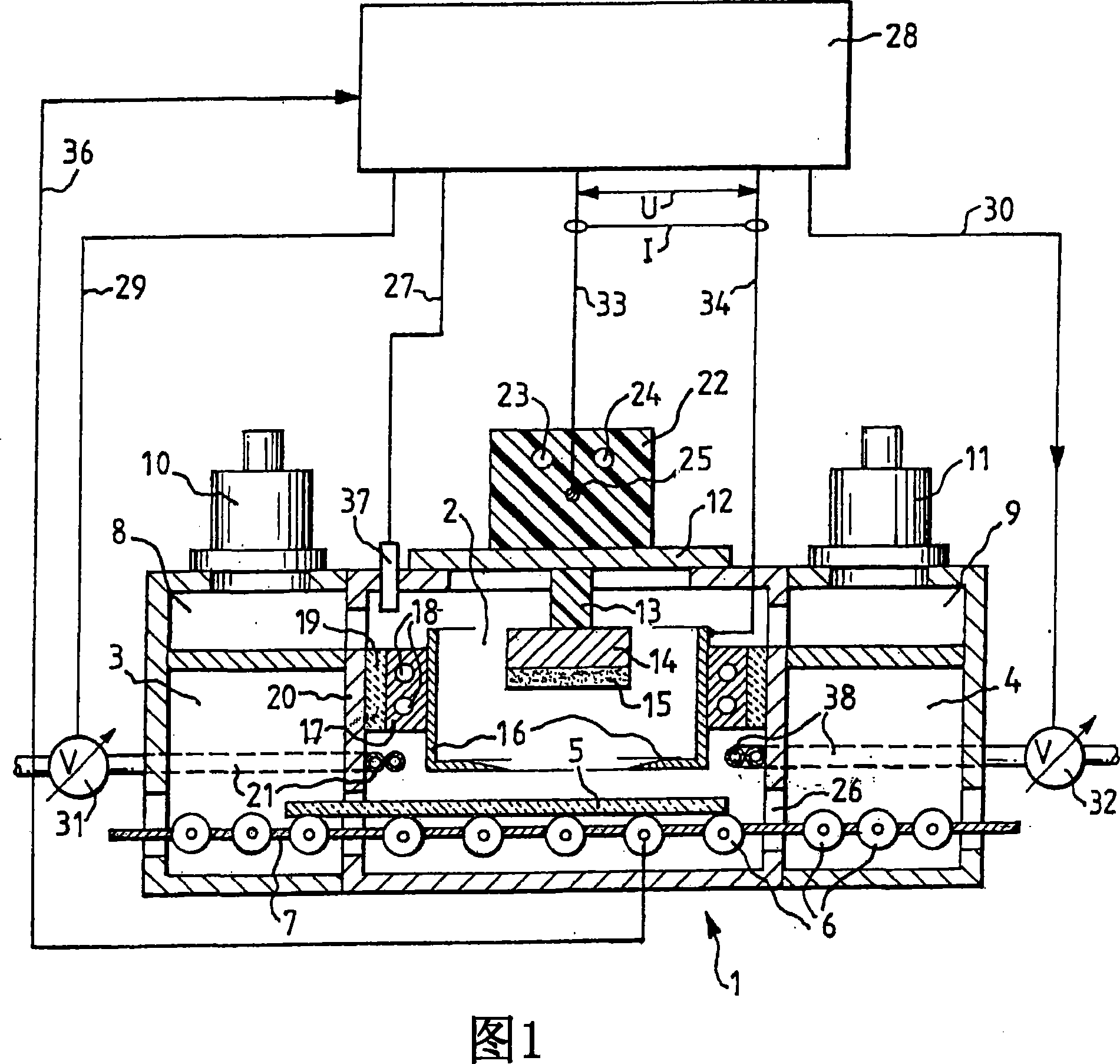
[0024] FIG. 1 shows a cross-section of a sputtering chamber 1 in which the coating of a substrate takes place. This sputtering chamber 1 comprises a special coating chamber 2 and two buffer chambers 3 , 4 . Adjacent to this sputtering chamber 1 there may be further sputtering chambers to the right and / or left thereof, not shown here. The substrate 5 is conveyed from left to right by the conveying rollers 6 supported by the bracket 7 . Above each of the buffer chambers 3 , 4 a pumping chamber 8 , 9 is arranged, and above each pumping chamber 8 , 9 a pump 10 , 11 is arranged.

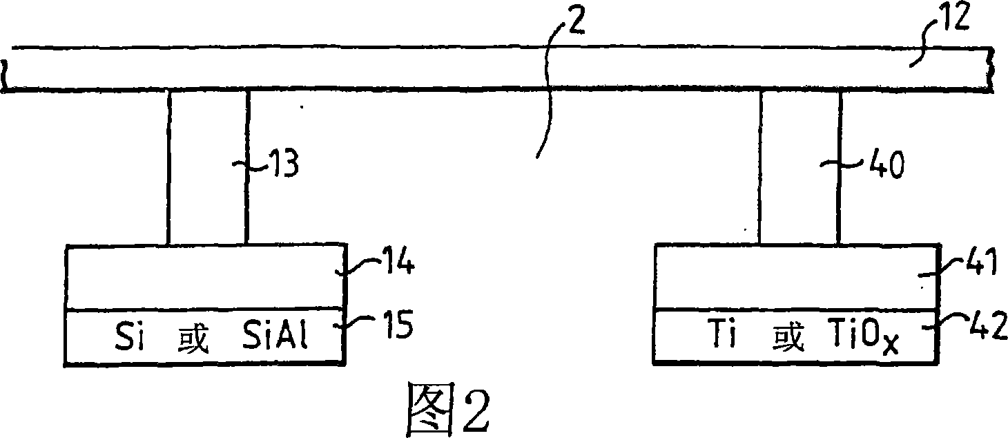
[0025] Mounted between the pumps 10 , 11 is a mounting cover 12 , to whose bottom a cathode support 13 is fastened, which supports a cathode 14 with a target 15 . The target 15 consists of silicon, aluminum and titanium or a combination of silicon and titanium only. The anode 16 below the target 15 is fixed on a support 17 which includes a cooling system 18 and is connected to the wall 20 of the coatin...


PUM


Abstract

The invention relates to a target material for the production of a protective layer for a solar control and absorption layer by means of sputtering. This target material is comprised of silicon doped with titanium. The protective layer, which can be produced with the target material, is heatable without significant changes of its properties. It is therefore also suitable for coating lass, which is heated and subsequently bent.

Description

technical field [0001] The invention relates to a target material according to the preamble of patent claim 1 and its use. [0002] It relates to the field of glass coatings, in particular glass coatings with heat-treatable sun protection coating systems. Background technique [0003] The curved coated glass is used for a variety of purposes. Such uses are, for example, curved window panes as shop window panes in corners of buildings. The process of uniformly coating curved glass is technically very difficult. Therefore, attempts have been made to first coat the glass and subsequently deform it. However, the problem encountered is that the coating peels off or bubbles form. Peeling or bubbling problems also occur with flat architectural glass that only needs to be warmed. Architectural glass is formed by heating for a few minutes to a temperature of about 700°C, followed by rapid cooling. When the glass is broken, the glass shatters into many small glass fragments due ...

Claims


Application Information

Patent Timeline
Patent Type & Authority Applications(China)
IPC IPC(8): C23C14/34C03C17/36C03C17/34C23C14/06C23C14/35
CPCC03C17/36C03C17/366C03C2217/212C23C14/0676C03C17/3639C03C2217/23C23C14/352C03C17/3618C03C2217/213C23C14/3414C03C17/3411C03C17/3649C03C2217/214C03C2218/156
Inventor 耶德·克莱德艾特安东·兹梅尔蒂迈克尔·盖斯勒
Owner APPLIED MATERIALS INC
Why Eureka
Try Eureka