
Portable electric plane

A portable, electric planing technology, applied in the direction of manual planing, etc., can solve the problems of inconvenience, labor intensity and safety hazards, and achieve the effect of convenient operation, increased operation safety and efficient planing

Inactive Publication Date: 2007-05-16
JIANGSU GOLDEN HARBOUR ENTERPRISE LTD
View PDF0 Cites 6 Cited by
  • Summary
  • Abstract
  • Description
  • Claims
  • Application Information

AI Technical Summary

Problems solved by technology

In addition to pushing the machine forward with a hand-held electric planer, the operator also needs to lift the machine back to the planing starting point from time to time, and prevent cables from being entangled by the machine blade during the process of lifting the machine, which has considerable labor intensity and certain safety hazards
In addition, when the switch is turned off, the blade of the machine will continue to rotate for a period of time due to inertia. In order to prevent misuse and damage to the blade, it is very inconvenient to place the machine after the blade has completely stopped.

Method used


Image

  • Portable electric plane
  • Portable electric plane
  • Portable electric plane

Examples


Embodiment Construction

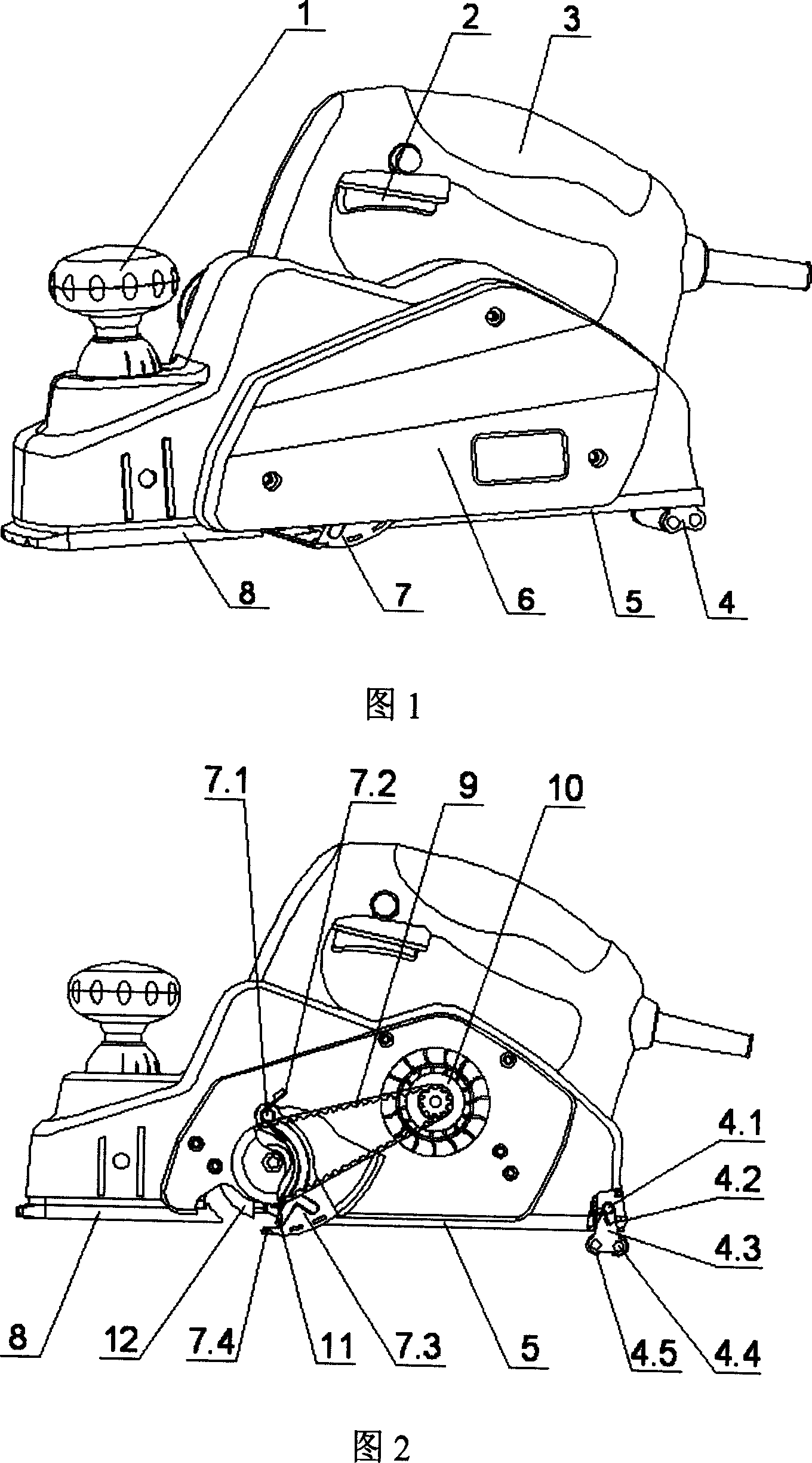
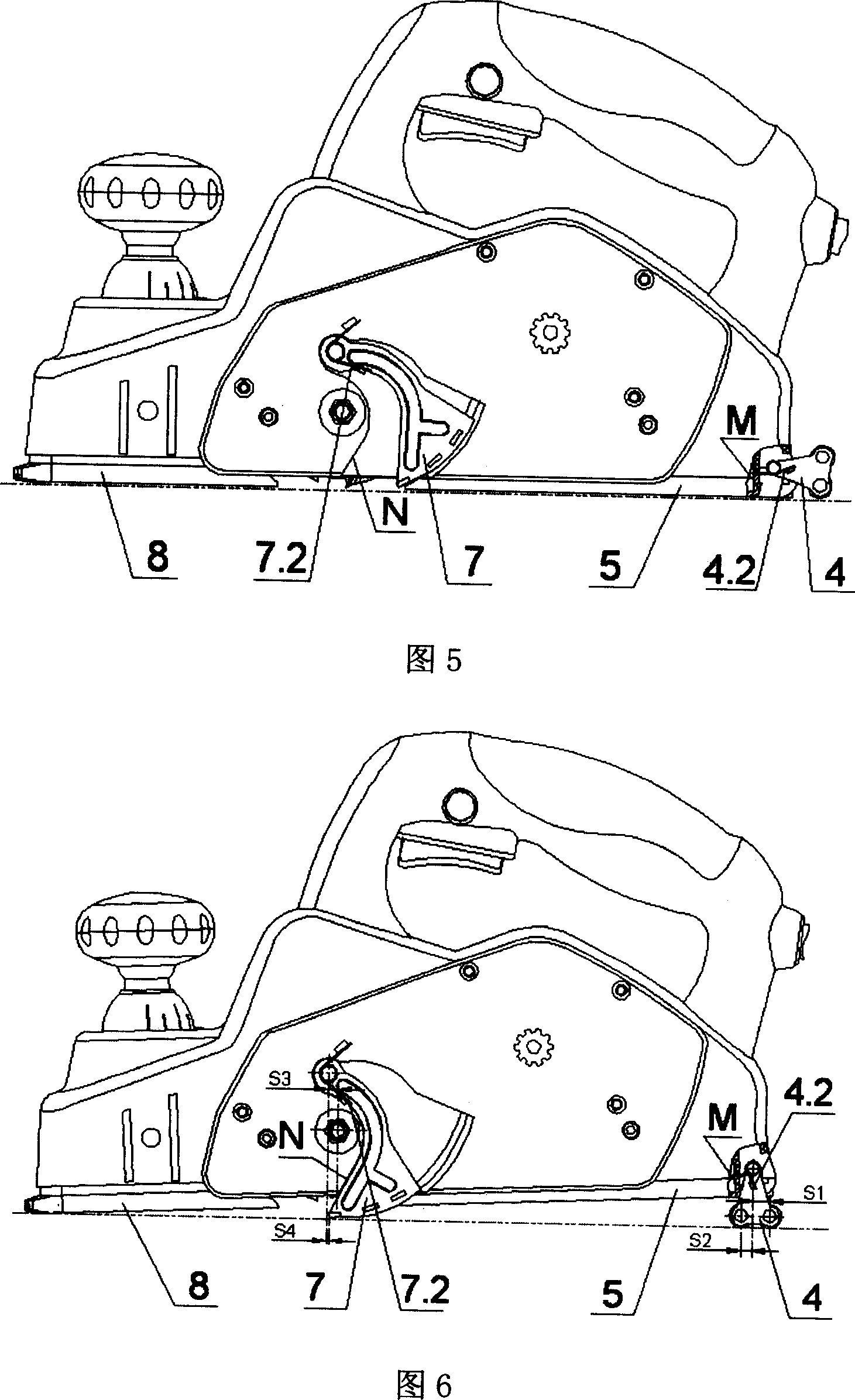
[0022] As shown in Figure 1 and Figure 2, a hands-free portable electric planer mainly includes a motor 10, a belt 9, a knife shaft 12, a blade 11, a bottom plate 5, an adjustment bottom plate 8, a depth adjustment knob 1, a switch 2, and a handle 3 , Roller bracket mechanism 4 and blade guard 7 etc. are formed, and roller bracket mechanism 4 is positioned at machine afterbody, and the shield of blade guard 7 rotates to below the blade.

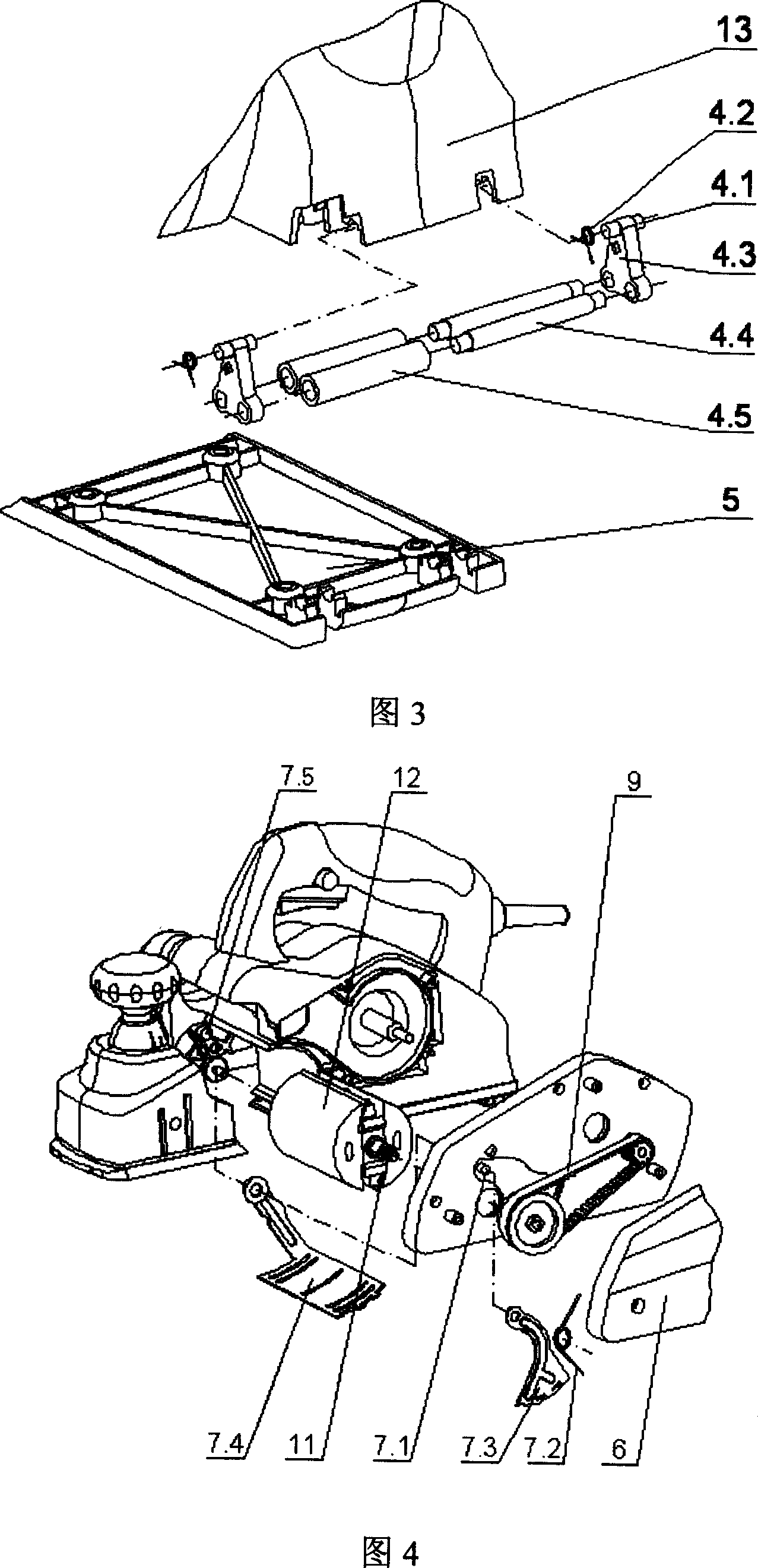
[0023] As shown in Figure 3, the portable electric planer is equipped with at least one roller bracket mechanism, and the roller bracket mechanism 4 is composed of bracket 4.3, bracket rotating shaft 4.1, roller shaft 4.4, roller 4.5 and bracket torsion spring 4.2, etc., wherein There are at least two roller shafts and at least one torsion spring. The bracket rotating shaft 4.1 is located on the upper part of the bracket 4.3 and hinged in the mounting hole between the machine tail casing 13 and the bottom plate 5. The roller bracket mechanism ...


PUM


Abstract

The invention relates to a portable electric planer, formed by motor, belt, blade axle, blade, bottom plate, adjust bottom plate, depth adjust knob, switch and handle, wherein the invention also comprises a roller support and a blade protector. The roller support is at the tail of device; the mask of blade protector can rotate to be under the blade. The invention can avoid lifting device to leave work piece surface when backwards planning into the start, but directly along the surface of work piece, with high efficiency. And the invention can avoid taking in cable by blade, to improve the safety.

Description

technical field [0001] The invention relates to an electric planer, in particular to a portable electric planer, and belongs to the technical field of electric tool manufacturing. Background technique [0002] Portable electric planers are widely used in the field of wood processing. Its application improves work efficiency and reduces the labor intensity of operators. When the existing electric planer is working, the operator holds the machine forward and backward to carry out the operation. When the machine is forward, the bottom plate of the machine is close to the workpiece (wood) for planing. Then go planing forward. In addition to pushing the machine forward with a hand-held electric planer, the operator also needs to lift the machine back to the planing starting point from time to time, and also prevent cables from being entangled by the machine blade during the process of lifting the machine, which has considerable labor intensity and certain safety hazards. In add...

Claims


Application Information

Patent Timeline
Patent Type & Authority Applications(China)
IPC IPC(8): B27C1/10
Inventor 林有余
Owner JIANGSU GOLDEN HARBOUR ENTERPRISE LTD
Learn More