Using impedance in parts of living body for generating controlling signal for controllable device

A technology of controlling signals and controlling equipment, applied in the input/output of user/computer interaction, computer components, input/output process of data processing, etc., capable of solving differences or conscious changes, fluctuations in skin resistance, difficult equipment, etc. problem, to achieve low wiring costs, reliable impedance value change detection, and achieve the effect of impedance value change detection

Inactive Publication Date: 2007-05-16
KONINK PHILIPS ELECTRONICS NV
View PDF4 Cites 3 Cited by
  • Summary
  • Abstract
  • Description
  • Claims
  • Application Information

AI Technical Summary

Problems solved by technology

[0006] Such disadvantages are observed in this known method and in this known system: as pointed out earlier, appropriate mental training is required to implement this known method, in which only a limited number of users are able to achieve a truly assessable Differences or deliberate changes in skin resistance are used so that such changes in current resistance can be intentionally brought about by the user of an electronic device to control the device
Moreover, there is also a disadvantage that the skin resistance of the user of the personal or electronic device will have a large normal fluctuation, so that it is impossible to directly use the known method and the known system, and it is necessary to use the known method in advance according to the situation. method for users to match or trim
Another disadvantage of the known method is that it is difficult to use a uniform method parameter to control the device in the known method, considering that there are relatively large differences in the absolute value of the user's skin resistance.

Method used


Image

  • Using impedance in parts of living body for generating controlling signal for controllable device
  • Using impedance in parts of living body for generating controlling signal for controllable device
  • Using impedance in parts of living body for generating controlling signal for controllable device

Examples


Embodiment Construction

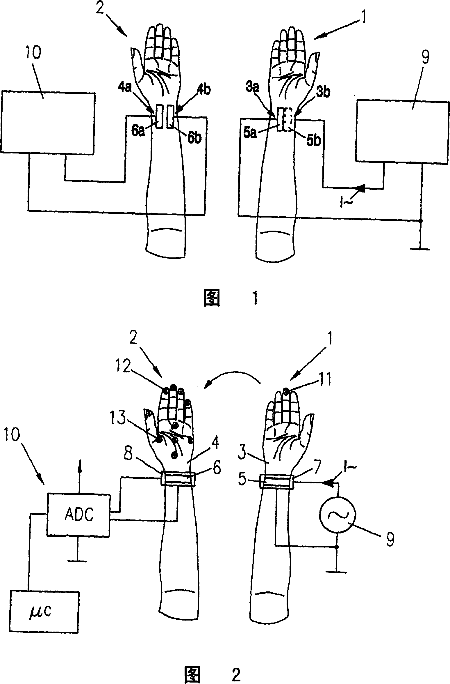
[0032] In the accompanying drawings 1 and 2, the right arm 1 and the left arm 2 of a person not drawn in detail are shown, wherein an electrically conductive first contact is arranged on the inner side of the forearm area in the forearm area of ​​the right arm 1 5a, and a conductive second contact 5b (indicated by dashed lines) is provided outside the forearm region, by means of which first contact 5a a conductive first connection is established with the first body region of the forearm region, and by means of This second contact 5b establishes a conductive second connection with the second body region of the forearm region. Moreover, in the forearm region of the left arm 2, a conductive third contact 6a and a conductive fourth contact 6b are provided on the inner side of the forearm region substantially parallel to each other and spaced apart from each other by a certain distance. With the help of point 6a, a conductive third connection is established with the third body regi...


PUM


Abstract

In such a method and system, firstly, at least an electrically conducting first connection to a first body area (3a) of the whole body of a living being is established and at least an electrically conducting second connection to a second body area (3b) of the whole body of the living being at a distance from the first body area (3a) and, secondly, a change takes place in the physical relation between at least one body part (1, 2) of the whole body and the whole body, which change in the physical relation causes a change to occur in the impedance value of a bioelectrical impedance, which bioelectrical impedance is present between the first body area (3a) and the second body area (3b) and, thirdly, a detection takes place of the change in the impedance value of said bioelectrical impedance, as a result of which occurrence of the change result information RI is obtained and, fourthly, the control signal (CTRS) is generated in dependence on the result information (RI).

Description

technical field [0001] The invention relates to a method for generating at least one control signal for controlling a controllable device, in which method at least an electrically conductive first connection is established with a first body region of the entire body of a living body and with the entire A second body region at a distance from the first body region on the body establishes at least an electrically conductive second connection. [0002] The invention furthermore relates to a system for generating at least one control signal for controlling a controllable device, having at least an electrically conductive first contact for establishing at least an electrically conductive first connection to a first body region of the entire body of a living being and having at least a conductive second contact for establishing at least a conductive second connection with a second body region at a distance from the first body region on the entire body of the living subject. [0003...

Claims


Application Information

Patent Timeline
Patent Type & Authority Applications(China)
IPC IPC(8): G06F3/00G06F3/01
CPCG06F3/014G06F3/017G06F3/011
Inventor T·格鲁伯
Owner KONINK PHILIPS ELECTRONICS NV
Why Eureka
Try Eureka