Radiating device comprising at least one adaptive rejection filter and antenna provided with said device

A filter and self-adaptive technology, applied in antennas, resonant antennas, electrical short antennas, etc., can solve problems such as inability to detect UWB pulses correctly, achieve the effect of improving the compactness of the antenna and reducing the cost of the antenna

Inactive Publication Date: 2007-05-16
THOMSON LICENSING SA
View PDF0 Cites 2 Cited by
  • Summary
  • Abstract
  • Description
  • Claims
  • Application Information

AI Technical Summary

Problems solved by technology

This makes it impossible to detect UWB pulses correctly

Method used


Image

  • Radiating device comprising at least one adaptive rejection filter and antenna provided with said device
  • Radiating device comprising at least one adaptive rejection filter and antenna provided with said device
  • Radiating device comprising at least one adaptive rejection filter and antenna provided with said device

Examples


Embodiment Construction

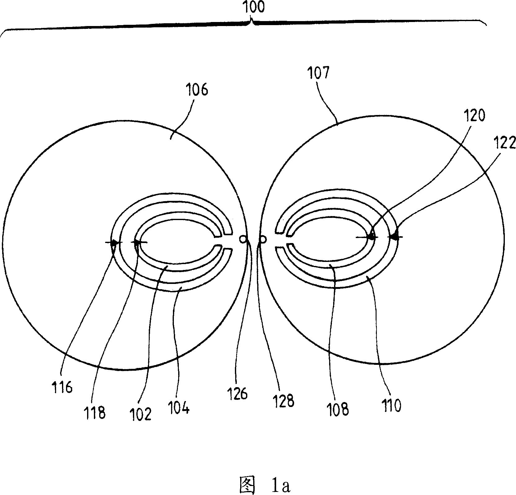
[0048] Fig. 1 shows an embodiment of a radiating device 100 of an antenna according to the invention. In this embodiment, the radiation device 100 includes a dipole antenna. This broadband radiating device 100 includes two circular arms 106 and 107 .

[0049] The diameter of the circular arms is 24 mm, while they are separated from each other by a distance of 1 mm. These round arms are made of or covered with conductive material.

[0050] The feed of these round arms is achieved through connection points 126 and 128 .

[0051] Two rejection filters have been integrated with this radiation device 100 .

[0052] The first one is located around the frequency of 4.6GHz: it is called the low frequency filter or LF filter.

[0053] This filter is made of two non-conductive parts 104 and 110, each having a length of 32 mm and a width of 0.5 mm.

[0054] The two non-conductive parts 104 and 110 are bridged by LF switching devices 116 and 122 which can be opened or closed. If the...


PUM


Abstract

The invention relates to an antenna comprising at least one radiating device (100) which is provided with a rejection filter associated with the frequency band of an interfering signal. The inventive antenna is characterised in that the rejection filter is adaptive in such a way that it is activated when the interfering signal is detected and the power thereof is greater than a threshold and said adaptive filter is deactivated when the detected power signal of the interfering signal is less than the threshold.

Description

technical field [0001] The invention relates to a radiating device comprising at least one adaptive rejector filter and an antenna comprising such a device. Specifically, the present invention is applied to wireless communication using high frequencies. Background technique [0002] Today, there are many wireless communication technologies for digital data transmission. Most conventional techniques are to modulate a high-frequency carrier with these digital data. [0003] The resulting signal is then amplified and sent to a transmit antenna. On receive, do the opposite. [0004] There are other information transmission techniques, in particular those that rely on the emission of Gaussian bursts of very short duration (of the order of 500 ps), the recurrence of which is accurately checked. The useful information to be transmitted is contained in the evolution of the period between successive pulses. [0005] This communication technique is known as Pulse Position Modulat...

Claims


Application Information

Patent Timeline
IPC IPC(8): H04B1/707H01Q9/28H01Q5/00H01Q5/50H01Q15/00H04B1/69
CPCH01Q15/0006H01Q15/0013H04B1/7163H01Q5/0093H01Q9/285H01Q5/50
Inventor 弗兰克·图多尔让-卢克·罗伯特让-伊维斯·利纳奥尔
Owner THOMSON LICENSING SA
Why Eureka
Try Eureka