Aperture coupled radiator and antenna including the same

a technology of coupled radiators and radiators, which is applied in the direction of antennas, electrical devices, antenna feed intermediates, etc., can solve the problems of increased manufacturing costs of radiators, and achieve the effects of reducing the manufacturing cost of antennas, enhancing the antenna yield, and reducing the manufacturing cost of radiators

Active Publication Date: 2016-06-21
ACE TECH
View PDF7 Cites 1 Cited by
  • Summary
  • Abstract
  • Description
  • Claims
  • Application Information

AI Technical Summary

Benefits of technology

[0022]A radiator of the present invention is not physically connected to a reflection plate or a feed track, and thus the possibility of PIMD is removed and the manufacturing cost of the radiator may be reduced. Accordingly, the yield of the antenna may be enhanced and the manufacturing cost of an antenna may be reduced.
[0023]In addition, since there is no soldering performed when manufacturing the radiator, no coating is required on the radiator. Hence, the manufacturing cost of the radiator may be reduced.
[0024]Furthermore, a base plate, feed section and a radiation element is manufactured through a simple method of bending a single piece of metal, and thus the time and cost required for manufacturing the radiator may be reduced.

Problems solved by technology

As a result, the manufacturing cost of the radiator is increased.

Method used


Image

  • Aperture coupled radiator and antenna including the same
  • Aperture coupled radiator and antenna including the same
  • Aperture coupled radiator and antenna including the same

Examples


first embodiment

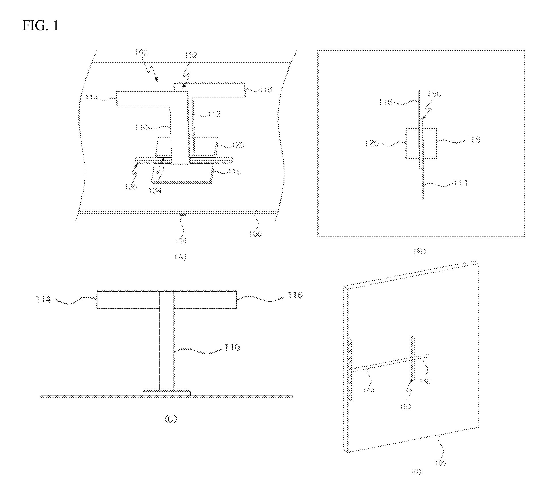
[0038]FIG. 1 is a perspective view illustrating an antenna according to the present invention.

[0039]In FIG. 1(A), an antenna of the present embodiment is for example an antenna for a base station, and includes a reflection plate 100, a radiator 102 and a feed track 104. Only one radiator 102 is shown in FIG. 1, but plural radiators may be disposed on the reflection plate 100. Hereinafter, it will be assumed that one radiator 102 is disposed on the reflection plate 100 for convenience of description.

[0040]The reflection plate 100 functions as a reflector and a ground. In one embodiment of the present invention, a slot 130 as one example of an aperture is formed on the reflection plate 100 as shown in FIG. 1(A) and FIG. 1(B). Here, the slot 130 may have various shapes such as a rectangular shape, etc. The length and width of the slot 130 may be varied to optimize the coupling between the feed track and the radiator feed and for impedance matching.

[0041]The radiator 102 is disposed on ...

second embodiment

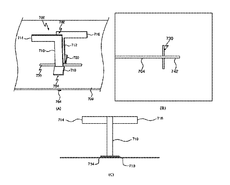
[0071]FIG. 7 is a perspective view illustrating an antenna according to the present invention.

[0072]In FIG. 7(A) and FIG. 7(B), the antenna of the present embodiment includes a reflection plate 700, a radiator 702 and a feed track 704.

[0073]Since the elements other than the radiator 702 in the present embodiment are the same as those in the first embodiment, further descriptions concerning the same elements will be omitted.

[0074]The radiator 702 includes feed sections 710 and 712, radiation elements 714 and 716, base plates 718 and 720 and a supporting section 734.

[0075]The supporting section 734 supports the base plates 718 and 720 as shown in FIG. 7(C), preferably two divided sub-supporting sections support the base plates 718 and 710, respectively.

[0076]In one embodiment of the present invention, the supporting section 734 is made from a certain dielectric substance, e.g. Poly Tetra Fluoro Ethylene (PTFE) spacer. Here, the size of the base plates 718 and 720 when the supporting s...

third embodiment

[0081]FIG. 10 is a perspective view illustrating an antenna according to the present invention.

[0082]In FIG. 10(A) and FIG. 10(B), the antenna of the present embodiment includes a reflection plate 1000, a radiator 1002 and a feed track. Since structure of the backside of the reflection plate 1000 including the feed track is the same as in the first embodiment, the structure of the backside is not shown.

[0083]The radiator 1002 includes a first feed section 1010, a second feed section 1012, a first radiation element 1014, a second radiation element 1016, a first base plate 1018 and a second base plate 1020.

[0084]In one embodiment of the present invention, a supporting section 1034 may be disposed between the base plates 1018 and 1020 and the reflection plate 1000 as shown in FIG. 10(C), i.e. the supporting section 1034 supports the base plates 1018 and 1020. Here, the supporting section 1034 may be made from a PTFE dielectric substance.

[0085]In another embodiment of the present invent...


PUM


Abstract

A radiator in which power is fed through a slot of a reflection plate and which can be manufactured in a simple manner and an antenna including the same are disclosed. The antenna includes a reflection plate and a radiator. The radiator includes feed sections disposed on a first surface of the reflection plate, first and second radiation elements extending perpendicular to the feed section or inclined towards the reflection plate, and first and second base plates configured to support the balanced parallel strip feed sections. Here, the first and second base plates are capacitively coupled to the reflection plate.

Description

TECHNICAL FIELD[0001]Example embodiments of the present invention relate to an aperture coupled radiator and an antenna including the same, and more particularly relate to a radiator to which a power is fed through a slot (aperture) of a reflection plate for simple manufacture and an antenna including the same.BACKGROUND ART[0002]An antenna, especially an antenna for a base station, includes a plurality of radiators, and transmits / receives a signal by using a beam outputted from the radiators. Generally, the radiators are connected directly to a reflection plate which functions as a ground, and so a passive intermodulation distortion (PIMD) due to contact of metals may occur.[0003]In addition, since a feed line for feeding the power to the radiator is physically connected to a balun section of the radiator through soldering, the radiator may need to be coated with a certain substance (e.g. tinning) so as to perform the soldering. As a result, the manufacturing cost of the radiator i...

Claims


Application Information

Patent Timeline
Patent Type & Authority Patents(United States)
IPC IPC(8): H01Q19/10H01Q9/16H01Q1/50
CPCH01Q1/50H01Q9/16H01Q19/108
Inventor KITCHENER, DEAN
Owner ACE TECH
Why Eureka
Try Eureka