
Piezoelectric resonant diaphragm type sensor

A piezoelectric resonance and diaphragm type technology, applied in the field of sensors, can solve the problems of inability to apply icing detection, limitation, and inability to install wings flush with each other, and achieve the effects of low power consumption, small size, and stable operation

Inactive Publication Date: 2007-05-23
HUAZHONG UNIV OF SCI & TECH
View PDF0 Cites 10 Cited by
  • Summary
  • Abstract
  • Description
  • Claims
  • Application Information

AI Technical Summary

Problems solved by technology

The application of this kind of icing sensor is limited. If it is used in an aircraft, it cannot be installed flush on the surface of the wing, etc., and can only be protruded in the air.
This sensor also cannot be used for icing detection on airport runways and roads

Method used


Image

  • Piezoelectric resonant diaphragm type sensor
  • Piezoelectric resonant diaphragm type sensor
  • Piezoelectric resonant diaphragm type sensor

Examples


Embodiment Construction

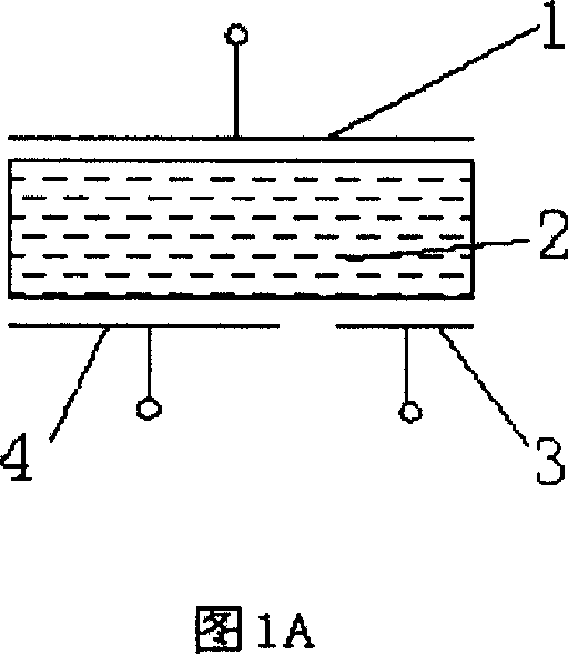
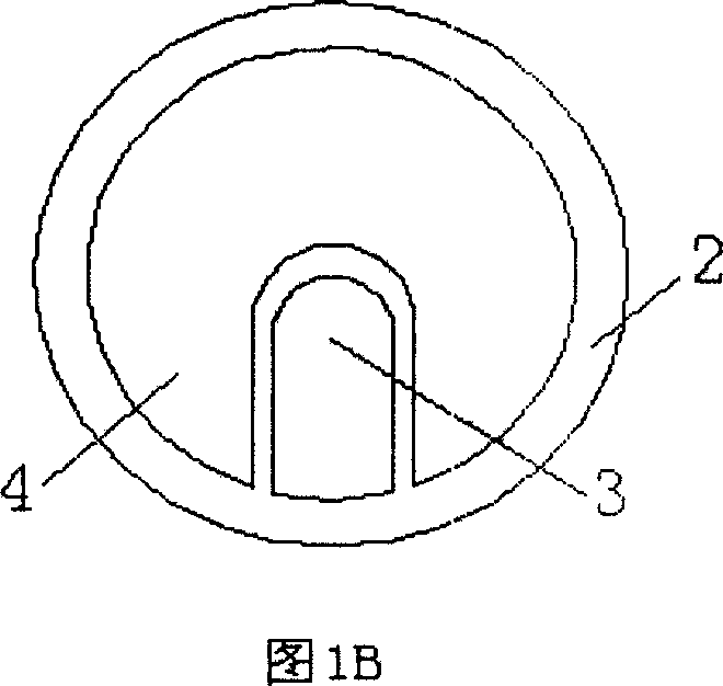
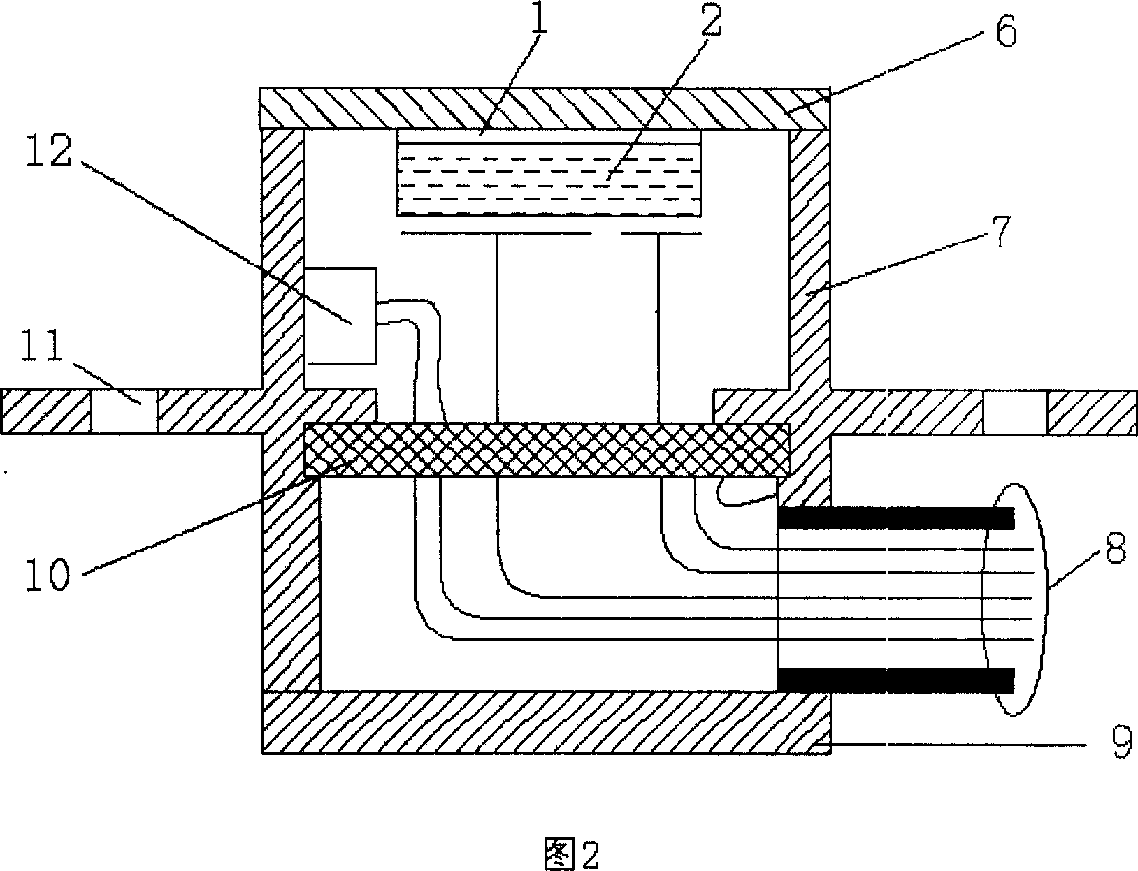
[0016] Embodiments of the present invention will now be described with reference to FIG. 1A , FIG. 1B , FIG. 2 , and FIG. 3 .

[0017] Fig. 1A and Fig. 1B are a kind of three-electrode radial expansion and deformation vibration disc type piezoelectric element, the reference ground electrode 1 is circular and covers one side of the piezoelectric element body 2, and the other side of the piezoelectric element body 2 is the drive The electrode 4 is a small piece of signal electrode 3 divided from the drive electrode 4 . Each electrode is made of silver material and formed on the piezoelectric element body by sintering process.

[0018] Figure 2 shows an embodiment of the present invention, one end of the cylindrical stainless steel housing 7 is welded with a vibrating diaphragm 6, and the other end is closed by a back cover 9 to form a closed cavity; the vibrating diaphragm 6 is bonded with piezoelectric elements, piezoelectric The element is made of modified lead zirconate tita...


PUM


Abstract

The piezoelectric resonance diaphragm sensor belongs to the sensors, and it overcomes the limitation of the existing vibration tube icing sensor, for the detection of the icing phenomenon. In the invention, the tube stainless steel shell, one end jointing connects the vibration diaphragm, and another end forms a airtight cavity closed with the rear board; (1) the said vibration diaphragm is attached by the piezoelectric element, the airtight cavity wall abutting the piezoelectric element and vibration diaphragm installed temperature-detecting element, and the piezoelectric element and the temperature-detecting element electrical connect with the drive and signal detection circuit through shielding cable of the airtight cavity; (2) the said piezoelectric element comprises: the one surface of the piezoelectric element connects the reference ground electrode, and another surface connects the driven electrode and the signal electrode encircled by the driven electrode. The invention is high sensitivity for the ice layer detection, and low power consumption, and small size, and it can be installed flush on some detection surfaces, such as highways, aircraft wing leading edge, and so on.

Description

technical field [0001] The invention belongs to a sensor used for detecting icing phenomenon. Background technique [0002] Icing is a natural phenomenon that may cause harm. For example, icing on the runway will hinder the normal take-off and landing of the plane; icing on the road will cause the car to slip out of control and cause traffic accidents; Some parts of the body (such as the leading edge of the wing) are icy, which seriously threatens the safe flight of the aircraft. [0003] The icing sensor is an information acquisition device or device that detects whether icing occurs and the severity of icing. The existing icing sensor is based on the principle of the vibrating cylinder. The vibrating cylinder is made into a rod-type detection rod. The vibrating cylinder is driven by electromagnetic force to perform telescopic resonant motion. When there is icing on the detection rod, the resonant frequency of the vibrating cylinder There will be dips, and more dips mean ...

Claims


Application Information

Patent Timeline
Patent Type & Authority Applications(China)
IPC IPC(8): G01H11/08G01H13/00
Inventor 叶林张杰张洪
Owner HUAZHONG UNIV OF SCI & TECH
Learn More