
Heat sink

A heat dissipation device and heat dissipation fin technology, which is applied in the direction of heat dissipation fins, indirect heat exchangers, heat exchange equipment, etc., can solve the problems that the airflow cannot blow into the flow rate, the ambient temperature rises, and is slow, so as to ensure smoothness, Improve heat dissipation performance and increase the effect of heat dissipation area

Inactive Publication Date: 2007-05-23
FU ZHUN PRECISION IND SHENZHEN +1
View PDF0 Cites 15 Cited by
  • Summary
  • Abstract
  • Description
  • Claims
  • Application Information

AI Technical Summary

Problems solved by technology

However, increasing the heat sink density can increase the total heat dissipation area, but due to the denser structure of the heat sink, the wind resistance is greater, and most of the energy of the flowing gas is consumed by the stagnant flow generated by the narrow flow channel, resulting in airflow The heat cannot be blown into the fin group or the flow rate is slow, so the heat cannot be taken away in time, causing the temperature of the surrounding environment to rise, which seriously affects the heat dissipation efficiency of the heat sink; , to ensure the smoothness of the flow path, but due to the small heat dissipation area of ​​the heat dissipation device, the heat that can be exported is small, and the purpose of cooling electronic components cannot be achieved

Method used


Image

  • Heat sink
  • Heat sink
  • Heat sink

Examples


Embodiment Construction

[0014] The heat dissipation device of the present invention is used to dissipate heat from electronic components such as a central processing unit (not shown in the figure).

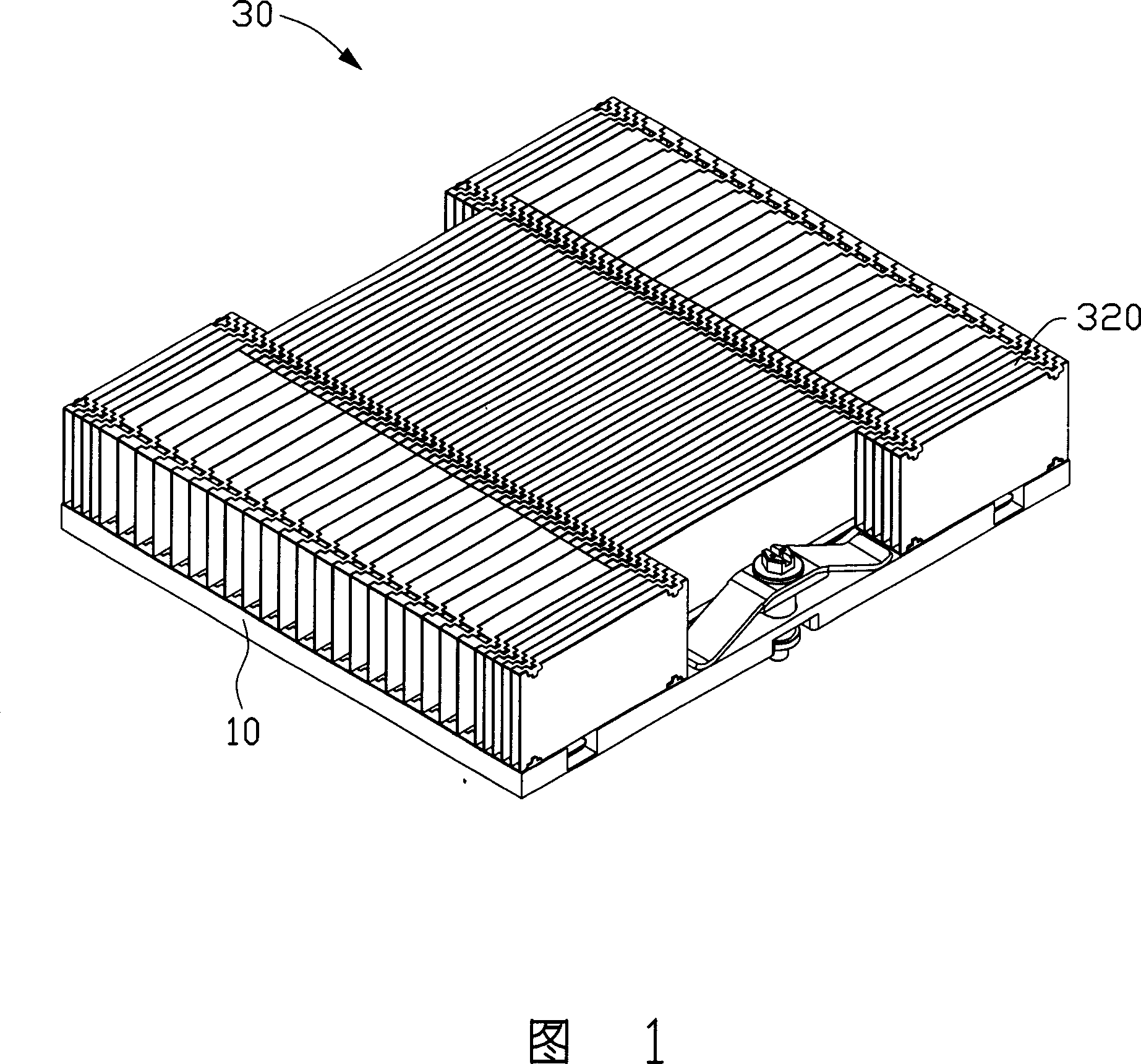
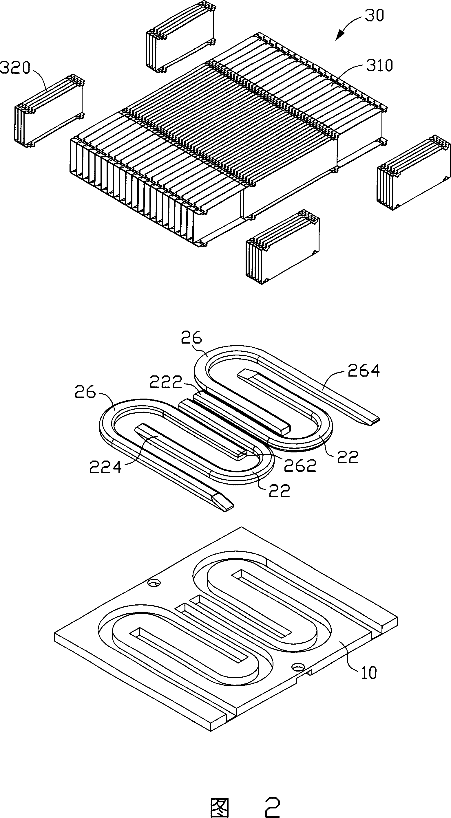
[0015] 1 to 4 show the first embodiment of the heat dissipation device of the present invention. The heat dissipation device includes a base plate 10 , a heat sink set 30 disposed on the base plate 10 , and two sets of heat pipes 22 , 26 sandwiched between the base plate 10 and the heat sink set 30 .

[0016] The bottom plate 10 is made of materials with good thermal conductivity, such as copper and aluminum, and its bottom surface is in contact with electronic components (not shown) to absorb heat generated by the electronic components during operation. Both the first heat pipe 22 and the second heat pipe 26 are bent into a U shape and are flat. The first heat pipe 22 includes an evaporating section 222 and a condensing section 224 with equal lengths, and the second heat pipe 26 includes an evaporating ...


PUM


Abstract

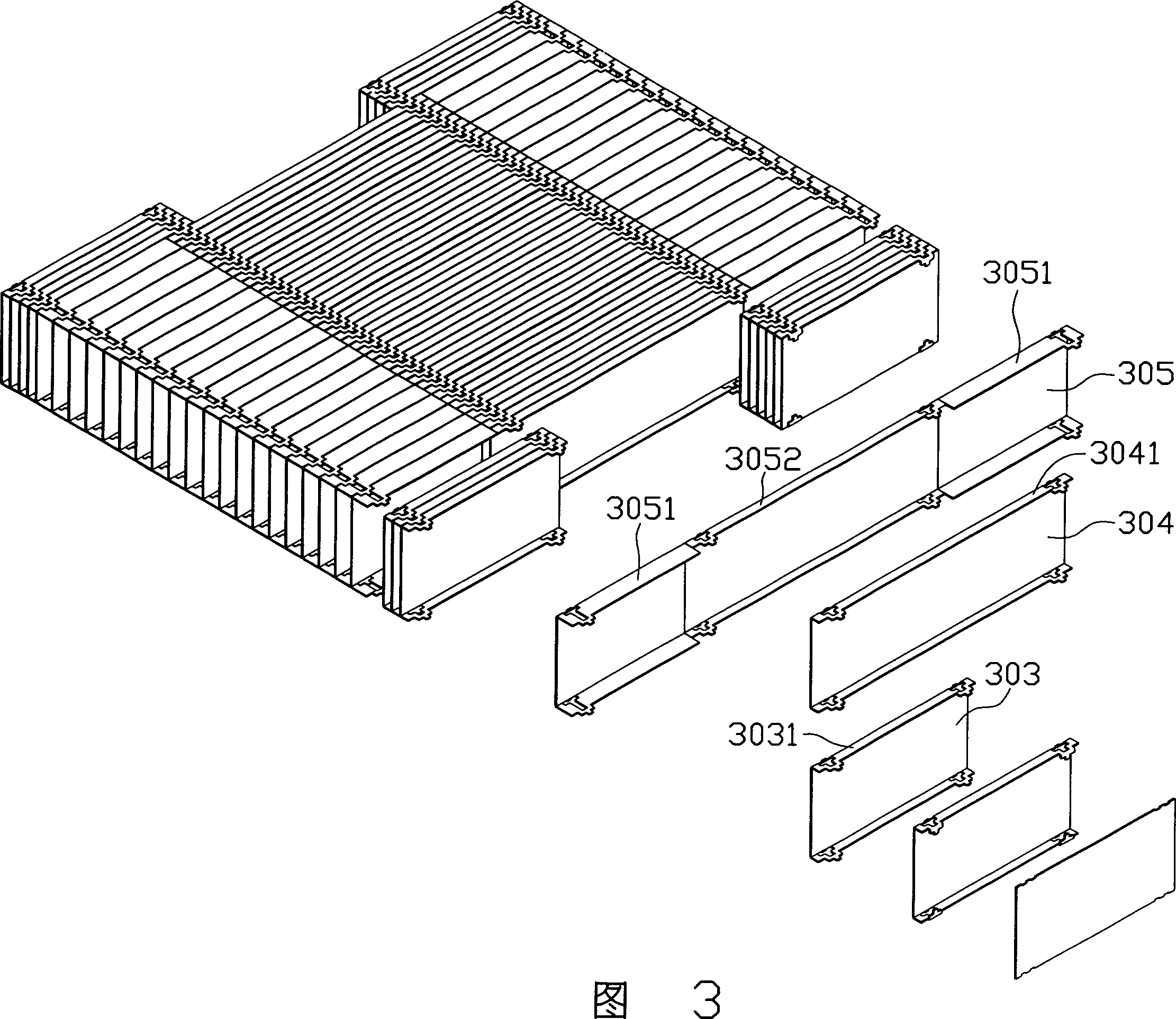
A heat-radiating device arranges for cooling the electronic component. The heat-radiating device comprises a baseboard, at lease two heat-conduction pipes, and a radiating fins module. One surface of the baseboard has the grooves suited the heat-conduction pipes, and the other surface contacts the electronic component. The radiating fins module is arranged vertically on the baseboard, the module comprising multiple radiating fins parallel arranged, and forms the flow passage structure with the middle fins dense and the two-side fins sparse for the middle fins locating just on the top of heat source. It can increase the heat-radiating area that heat source region adopts the dense structure, and it can decrease the wind resistance that the two-side adopts the sparse structure, and air stream can take out heat quantity in time. Hence, compared with traditional heat-radiating devices, the performance of the invention improves preferable.

Description

【Technical field】 [0001] The invention relates to a heat dissipation device, in particular to a heat dissipation device applied to electronic components. 【Background technique】 [0002] Electronic components (such as central processing unit) generate a lot of heat during operation, which increases the temperature of itself and the system, which in turn leads to a decrease in its operating performance. In order to ensure the normal operation of the electronic components, a cooling device is usually installed on the electronic components to dissipate the heat generated by them. [0003] A traditional cooling device generally includes a bottom plate in contact with electronic components, a plurality of heat sinks arranged on the bottom plate, and a fan installed on the top or side of the heat sink. The heat generated by the operation of electronic components is absorbed by the bottom plate, and then dissipated to the surrounding environment through the heat sink to cool the el...

Claims


Application Information

Patent Timeline
Patent Type & Authority Applications(China)
IPC IPC(8): G06F1/20H05K7/20
CPCH01L23/467H01L23/3672H01L23/427F28D15/0275F28F3/02F28F2215/04H01L2924/0002H01L2924/00
Inventor 夏万林李涛校敏奇钟勇
Owner FU ZHUN PRECISION IND SHENZHEN
Learn More