Electromagnetic residual current action protector and its protecting method

A residual current and electromagnetic technology, applied in the direction of automatic disconnection emergency protection device, emergency protection circuit device, protection switch operation/release mechanism, etc., can solve the problems of difficult assembly, low production efficiency, high scrap rate, etc., and achieve operation Convenience, reduced scrap rate, improved safety factor

Inactive Publication Date: 2007-05-23
LEGRAND LOW VOLTAGE ELECTRICAL APPLIANCES WUXI
View PDF0 Cites 12 Cited by
  • Summary
  • Abstract
  • Description
  • Claims
  • Application Information

AI Technical Summary

Problems solved by technology

[0003] In order to overcome the shortcomings of the existing electromagnetic residual current operating protector, such as the complexity of the operating mechanism, difficulty in assembly, low production efficiency and high rejection rate, the purpose of the present invention is to provide an electromagnetic residual current operating protector and its protection method. It is conducive to reducing the complexity of the mechanism, simplifying the assembly process and improving production efficiency, and can reduce the scrap rate of parts and finished products, thereby reducing production costs; at the same time, the separation of main and auxiliary circuits is obvious, which improves the safety factor of the whole machine

Method used


Image

  • Electromagnetic residual current action protector and its protecting method
  • Electromagnetic residual current action protector and its protecting method
  • Electromagnetic residual current action protector and its protecting method

Examples


Embodiment Construction

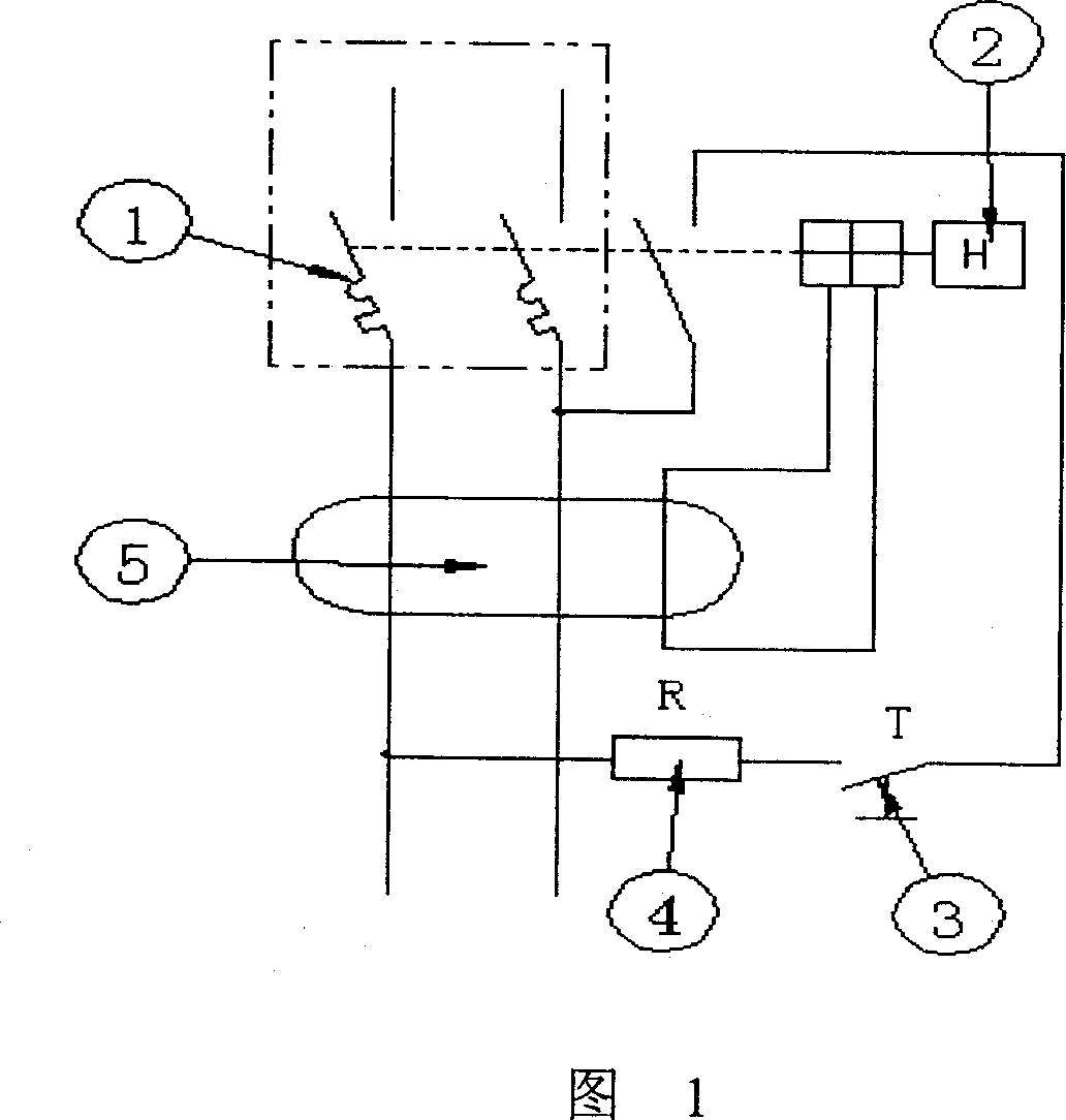
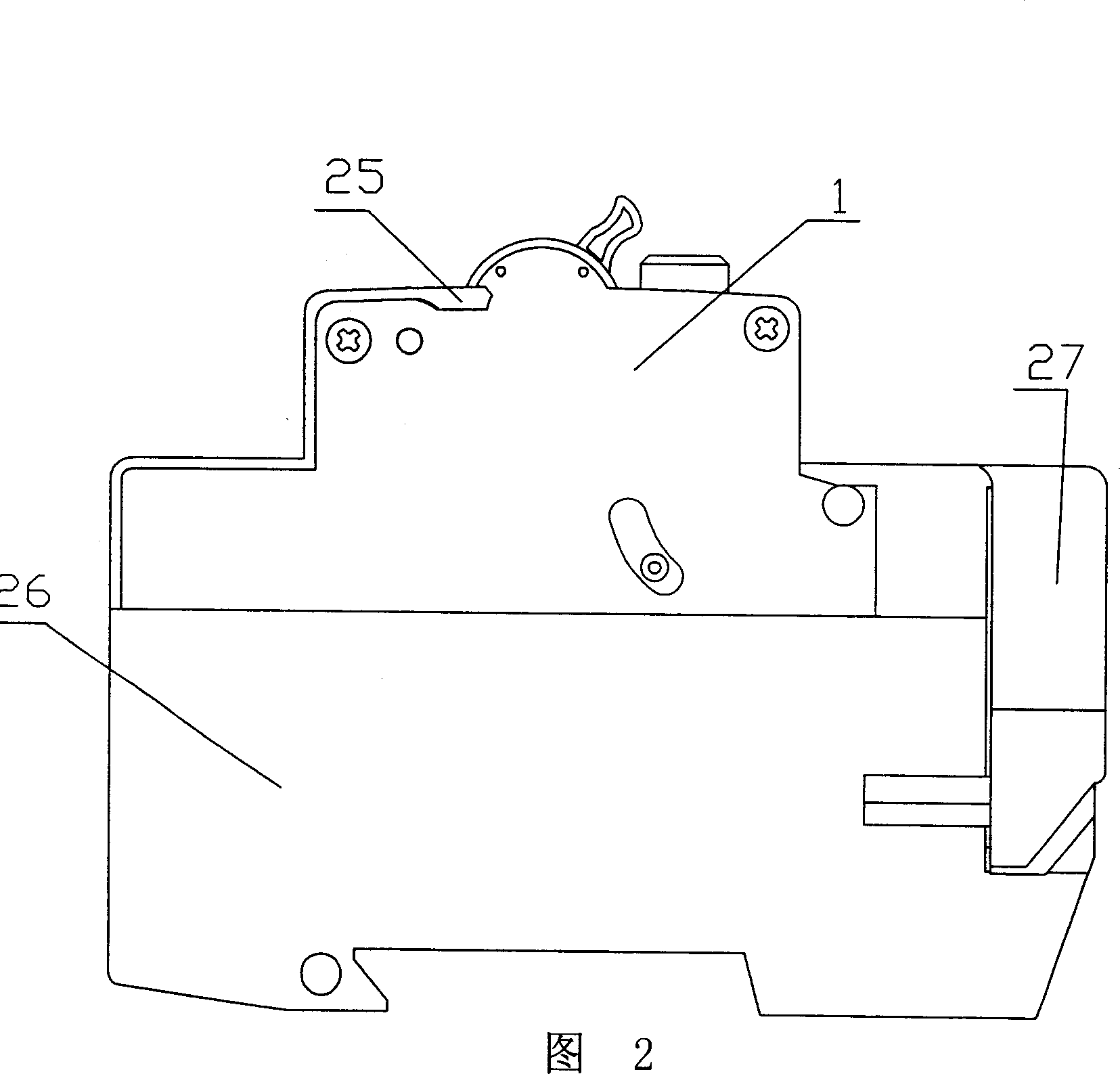
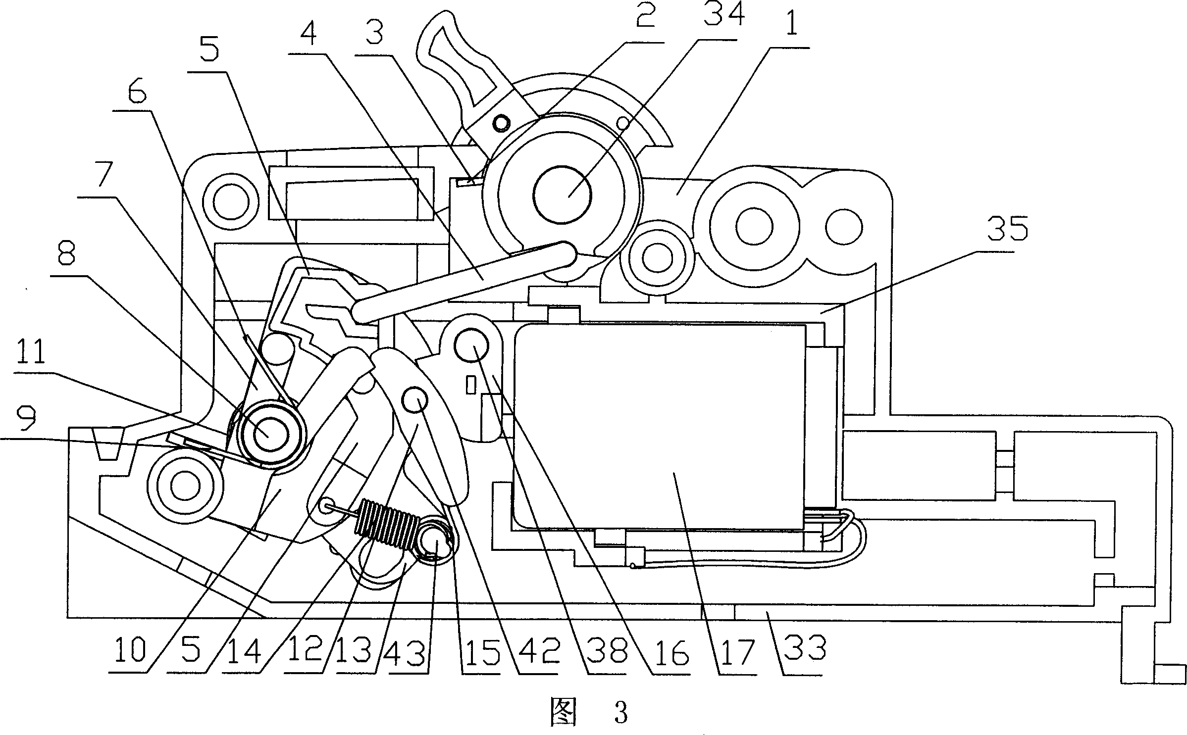
[0032] In the figure, 1. base, 2. handle, 3. spring, 4. connecting rod, 5. spoon-shaped jumper, 6. torsion spring, 7. Y-shaped jumper, 8. positioning shaft, 9. spring , 10. Turntable, 12. Rod jumper, 13. Jumper, 14. Extension spring, 15. Spring, 16. Reset, 17. Release, 18. Screw, 19. Press plate, 20. Screw , 21. Circuit breaker, 22. Transformer, 23. Test resistor, 24. Test button, 25. Cover, 26. Base, 27. Side plate cover, 28. Bus bar, 29. Side plate, 30. Transformer primary winding , 31. Terminal cover, 32. Terminal block, 33. Partition bar, 34. Shaft, 35. Positioning partition, 36. Moving contact piece, 37. Spring, 38. Reset shaft, 39. Serpentine protrusion, 40. Pin shaft, 41. Ditch, 42 small shaft, 43. Spring seat, 44. Cylindrical protrusion, 45. Through hole, 46. Transformer, 47. Card slot, 48. Contact, 49. Contact, 50. Lower step, 51. Upper step, 52. Cylinder, 53. Round hole, 54. Bearing, 55. Card, 56. Slope, 57. Ejector.

[0033] As shown in the figure: the electromagn...


PUM


Abstract

The invention relates to an electromagnetic current protector and relative method, wherein it has up and low structures; the low base is matched with track, while it contains mutual inductor, wiring base and main circuit; the up base is matched to mount executor and test circuit; the elements are tree layered in base and compressing plate while they are covered by compressing plate, and fixed via screw; the base and compressing plate are connected via one main axle; the elements rotate around main axle; the rotation disc is on two steps of base; the jump clamper and disc will operate via the spring force; the disc will not make whole device incline via the spring force. The invention has high reliability, while the return element and disc are matched via grooves, to prolong service life.

Description

technical field [0001] The patent of the present invention relates to a circuit protection device, especially capable of detecting residual current at the same time, and comparing the residual current with the residual operating current, and disconnecting the electromagnetic residual current of the protected circuit when the residual current value exceeds the residual operating current value. Current operated protector. Background technique [0002] At present, the operating mechanism of the electromagnetic residual current operating protector is mostly integrated, and the parts are scattered. The production process requires more process equipment, poor operability, repairability, and low utilization rate. At the same time, the separation of main and auxiliary circuits is not obvious, and the safety factor of the whole machine is low. Contents of the invention [0003] In order to overcome the shortcomings of the existing electromagnetic residual current operating protect...

Claims


Application Information

Patent Timeline
Patent Type & Authority Applications(China)
IPC IPC(8): H01H71/24H02H3/32
Inventor 晏国云潘万军韩瑄
Owner LEGRAND LOW VOLTAGE ELECTRICAL APPLIANCES WUXI
Why Eureka
Try Eureka