A permanent variable-resistance wind-driven generator

A generator and permanent magnet technology, applied in electrical components, electromechanical devices, electric components, etc., can solve the problems of reducing wind energy utilization efficiency, wind power generation efficiency, and generator starting resistance torque increase, so as to improve wind power generation efficiency , The effect of reducing the cost of constant frequency control

Inactive Publication Date: 2007-05-23
FLY RENEWABLE ENERGY TECH
View PDF0 Cites 0 Cited by
  • Summary
  • Abstract
  • Description
  • Claims
  • Application Information

AI Technical Summary

Problems solved by technology

However, a large rated wind speed corresponds to a large rated power of the generator, which increases the starting resistance torque of the generator, increases the cut-in wind speed, and reduces the wind power generation efficiency when the wind speed is lower than the rated wind spe

Method used


Image

  • A permanent variable-resistance wind-driven generator
  • A permanent variable-resistance wind-driven generator
  • A permanent variable-resistance wind-driven generator

Examples


Embodiment Construction

[0052] specific implementation plan

[0053] The present invention will be further described below in conjunction with accompanying drawing and embodiment:

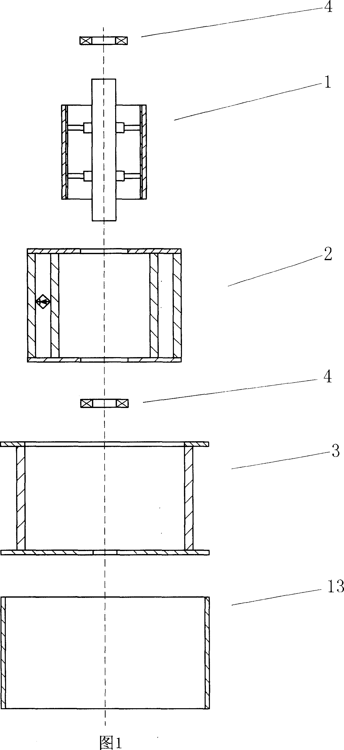
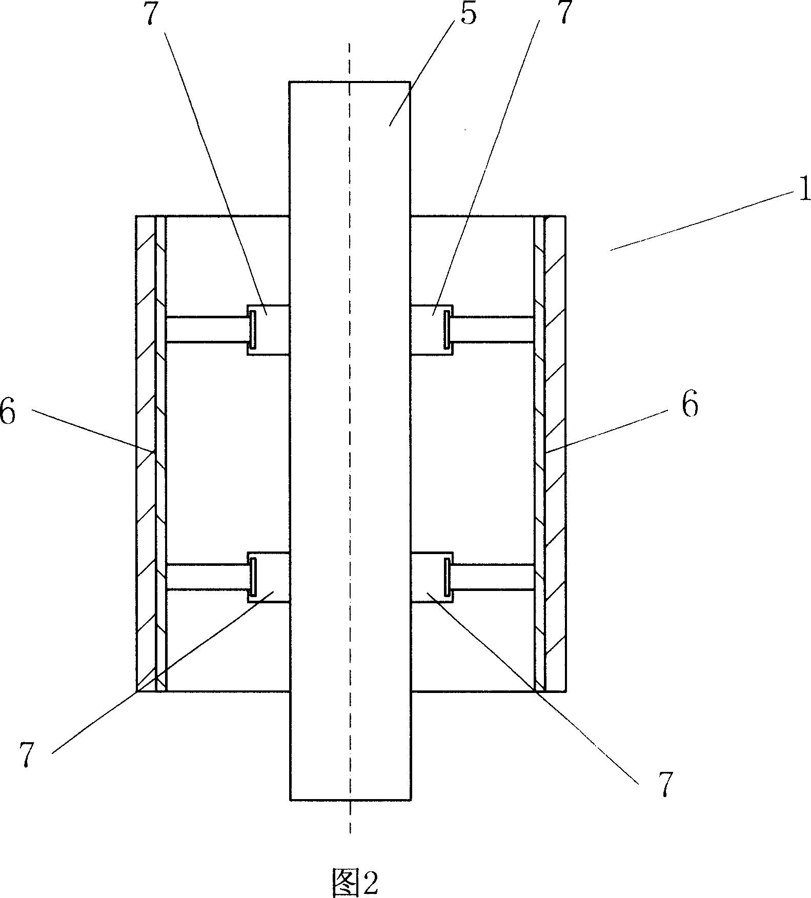
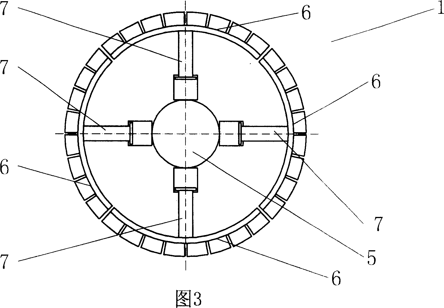
[0054]Figures 1 to 16 are schematic diagrams of main components and their structures of the present invention. Fig. 1 shows that the generator of the present invention is made up of permanent magnet stator 1, rotor 2, armature stator 3, bearing 4 and housing 13, and Fig. 2 and Fig. 3 show a kind of by main shaft 5, four arc-shaped Schematic diagram of the structure of a permanent magnet stator 1 composed of a magnet 6 and eight radial stroke drivers 7, and Fig. 4 and Fig. 5 show another permanent magnet composed of a main shaft 5, a circular magnet 6 and two end plates 24 The structure diagram of the stator 1, the structure diagram of a rotor 2 composed of a small armature 8, the electromagnet 9, the rectifier 11 and the end plate 10 shown in Figure 6 and Figure 7, the structure diagram of a rotor 2 composed of a large ...


PUM


Abstract

The invention relates to a wing permanent-magnetic (resistance-variable) generator, wherein via driver, the rotor and stator can obtain displacement, to control their electromagnetic induction, change magnetic resistance, generating power, torque and generating frequency, to match wind frequency and generator power, to improve generating efficiency, and reduce the cost in constant-frequency control. And it can generate large generating efficiency with low permanent magnet excitation.

Description

technical field [0001] The invention relates to a generator, in particular to a wind power generator. technical background [0002] Since the wind energy power varies with the cube of the wind speed, the output power of the fan varies widely with the wind speed. This feature of wind energy makes the power generation of wind turbines at cut-in wind speed and cut-out wind speed different by thousands of times, and the frequency changes by nearly a hundred times. [0003] The current wind turbines operate below the designed rated power, and the rated power of the wind generator usually corresponds to the rated wind speed; when the wind speed is higher than the rated wind speed, the control system of the fan changes the state of the wind blades to "overflow" part of the wind energy, making Wind turbines run at rated power to avoid burning out the generators. At this time, the "spillover" wind energy is not utilized. It can be seen that the rated wind speed is designed as the ...

Claims


Application Information

Patent Timeline
IPC IPC(8): H02K7/12H02K1/17H02K1/27
Inventor 李锋庞兵程钰张全德
Owner FLY RENEWABLE ENERGY TECH
Why Eureka
Try Eureka