Method for obtaining force and torque and doing work on load as well as device and application of method

A technology of torque and work, applied in the field of new energy, can solve problems that have not been practically applied

Pending Publication Date: 2021-03-19
黄竹山
View PDF0 Cites 0 Cited by
  • Summary
  • Abstract
  • Description
  • Claims
  • Application Information

AI Technical Summary

Problems solved by technology

[0005] For a long time, there have been many inventions of perpetual motion machines, but no practical application has been seen so far. Most of the inventions of perpetual motion machines violate scientific principles such as the first law of thermodynamics, the law of energy conservation, and the second law of thermodynamics.

Method used


Image

  • Method for obtaining force and torque and doing work on load as well as device and application of method
  • Method for obtaining force and torque and doing work on load as well as device and application of method

Examples


Embodiment 1

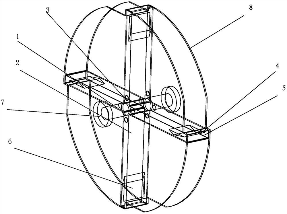
[0047] Embodiment 1; device A, fluid is air, tractor is motor, and load is generator; Motor, device, generator are fixedly connected in series with coaxial successively, wherein the rated output power of generator is greater than the rated input power of motor, neglecting friction Energy loss caused by sassafras, etc.

[0048] The working process is that the excitation circuit of the generator is opened, the motor is started, the drive device and the rotor of the generator rotate, and the excitation circuit of the generator is closed after the speed reaches the rated value, the generator works and outputs power;

[0049] To illustrate further with an example calculation,

[0050] Suppose, motor power P=10kw, speed n=3000rpm, torque T 0 =P / ω=10000 / 2 / π / 3000×60=32N.m, ω is the angular velocity, the radius of gyration of the end hole outside the cavity r 1 =0.3m, radius of gyration of inner hole r 2 =0.05m, 4 cavities are symmetrically distributed, each airfoil area s=0.3m×0.1m...

Embodiment 2

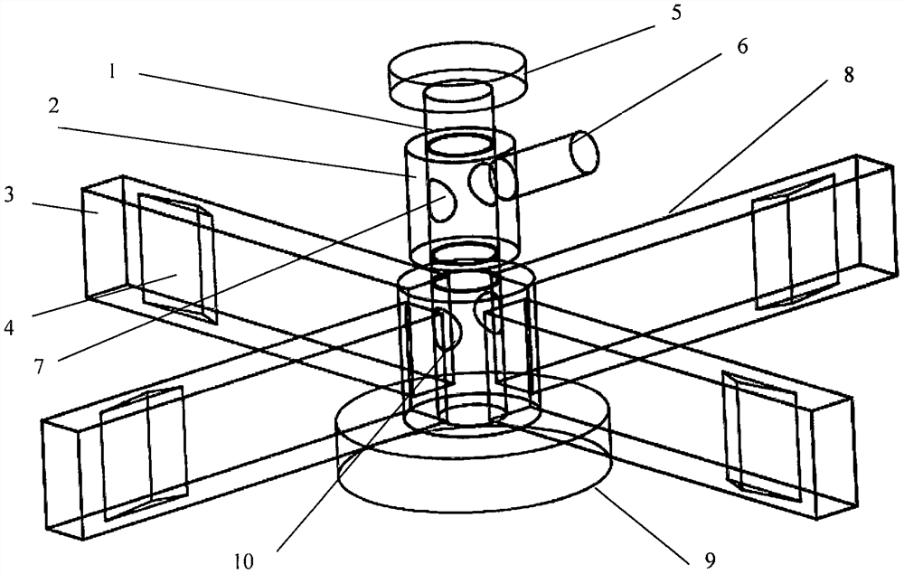
[0052] Embodiment 2; Apparatus B, fluid is air, and four cavity bodies revolve in the closed body, and device is connected with generator coaxially, suppose; The power P of the air extraction equipment on the closed body 1 =2.2Kw, air volume Q=18000m3 / h, this kind of fan is a very common fan in the market, the generator speed is 3000 rpm, the radius of rotation of the end hole outside the cavity is r=1m, and the four cavity bodies are symmetrically distributed. The area of ​​each airfoil s=0.3m×0.1m=0.03m 2 , the thrust arm of the airfoil part is L=0.8m, the lift coefficient of the airfoil part is c=0.8, and the area of ​​the outer end hole of each cavity is S 1 =0.3m×0.1m=0.03m 2 , the following ignores the energy loss caused by friction, etc., and the calculation results are rounded up;

[0053] Calculation; the sum of the area of ​​the outer end holes of the four cavities S 2 =0.03×4=0.12m 2 , the air flow velocity V=Q / S in the inner cavity of the cavity and the outer e...

Embodiment 3

[0054] Embodiment 3: Device A is connected with the main shaft of the machine tool, the output shaft of the internal combustion engine, the input and output shafts of the gearbox, and the motor of the air conditioner compressor in series connection or multi-axis connection, and transmits increased torque, and the output power is greater than the input power.

[0055] Take the machine tool as an example to illustrate the calculation; the machine tool is a vertical machining center, and the spindle power is P 0 =15Kw, the spindle speed is n=10000rpm, the spindle motor torque is 15.N.m at this speed, the device is fixed and connected in series with the machine tool spindle coaxially, the size of the device; r 1 = 0.15m, r 2 =0.03m, 4 cavities, the area of ​​each airfoil is s=0.2m×0.1m=0.02m 2 , the moment arm of the airfoil part is L=0.1m, the lift coefficient of the airfoil part is 0.8, and the influence of resistance such as frictional force is ignored, and the calculated resu...


PUM


Abstract

The invention discloses a method for obtaining force and torque and acting on a load as well as a device and application of the method, and belongs to the fields of new energy, electric vehicles, clean energy power generation, rotary machinery, perpetual motion machines and the like. The method is characterized in that wing-shaped parts are fixedly arranged in an inner cavity of a cavity body capable of doing rotary motion around a shaft, when a fluid flows through the cavity, the wing-shaped parts is forced, the force generates torque on a rotating shaft, and the device acts on a load when being connected with the load to work. When the device manufactured by the method is connected with a rotating electromechanical component to form an assembly to work, the assembly transmits a torque greater than that of the rotating electromechanical component, and the output power is greater than the input power; or flowing fluid with a power source flows through the cavity , the wing-shaped partsobtain thrust and generates torque, and the output power of the wing-shaped parts is larger than the input power of the flowing fluid power source. The device is combined with a generator to form a perpetual motion machine capable of doing work. The device can be used as a power source of mobile equipment, and application of the device for power generation is a brand-new clean energy power generation mode.

Description

technical field [0001] The invention belongs to the fields of new energy, electric vehicles, clean energy power generation, rotating electromechanical products, perpetual motion machines that perform work on loads, and the like. Background technique [0002] In recent decades, energy shortage and environmental pollution have become the focus of world attention. Due to the excessive application of fossil energy, a large amount of carbon dioxide emissions, global warming, extreme weather, and frequent natural disasters, countries all over the world are changing the traditional high energy consumption. , high-pollution economic growth mode, vigorously promote the application and production of clean energy and renewable energy. [0003] my country also attaches great importance to the development and utilization of clean energy and new energy. The government vigorously promotes the gradual replacement of traditional fuel vehicles with electric vehicles and hydrogen vehicles, and...

Claims


Application Information

Patent Timeline
Patent Type & Authority Applications(China)
IPC IPC(8): H02K53/00
CPCH02K53/00Y02T10/7072
Inventor 黄竹山
Owner 黄竹山
Why Eureka
Try Eureka